An unusual air producer/ generator as nothing is quite as it seems.
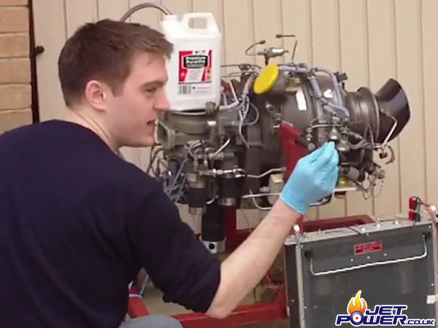
The Williams WR27-1 APU is used as an air producer for starting the S3 Viking Anti Submarine Aircraft, it is also equipped with a not so handy 600Hz generator.

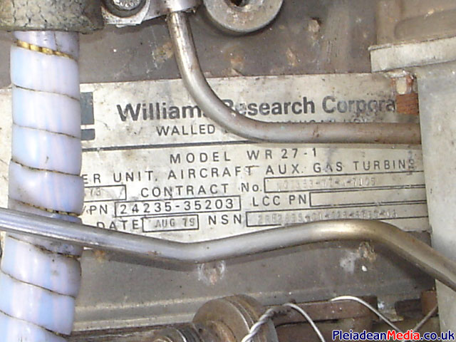
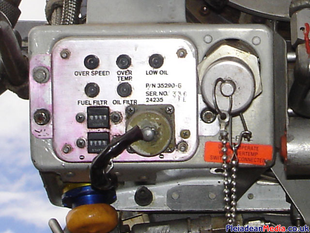
Serial & Identification Plate.
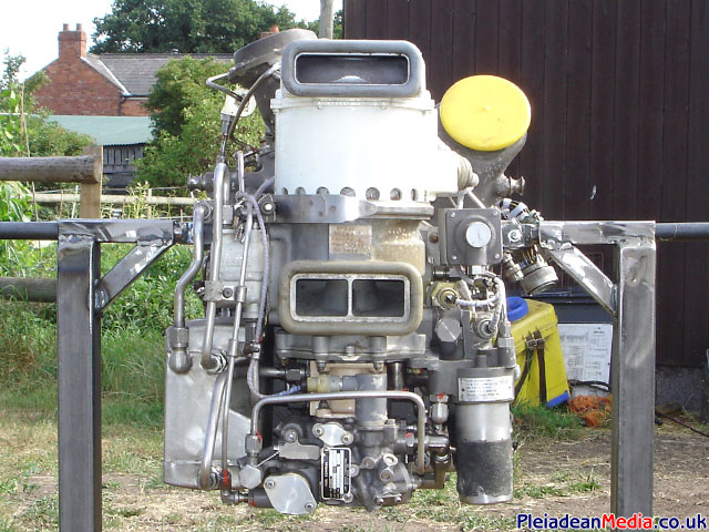
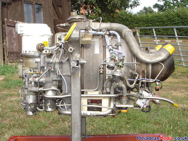
Front view showing from the top, generator with the air cooling inlet at the top with the warm air exiting from the round holes at the bottom. Then there’s the air producer outlet to its right with the yellow cover. The holes in the center are the air cooling inlets for the oil cooler and below that are the oil and fuel pumps with the filter bowls to the bottom right. The oil tank is bottom left.
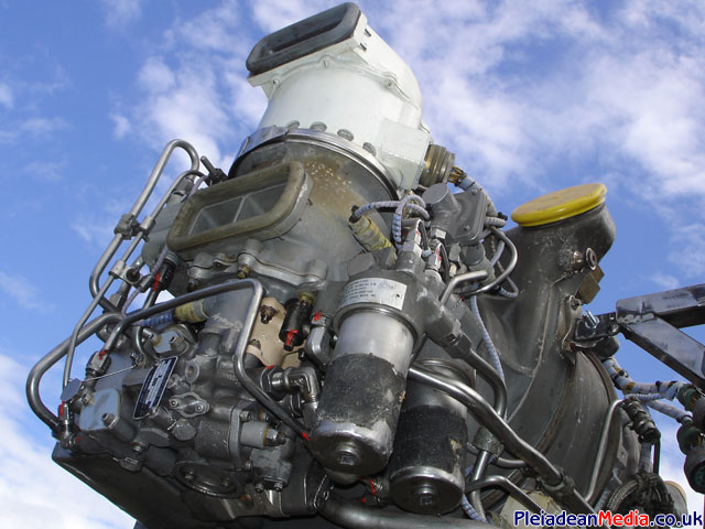
Fuel and Oil pumps with the oil and fuel bowls nearest the camera.
The white box at the bottom is the igniter exciter, the large pipe to its bottom and right is the hydraulic starter oil feed and on the top are the air start overflow/ spill pipes.
Bottom right is the oil tank with the oil cooler mounted just above it.
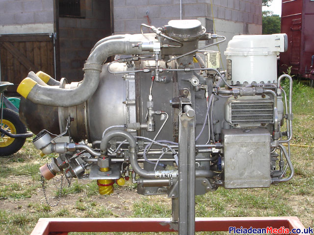
Bottom right the control pane can be seen.
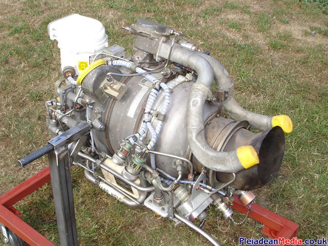
Visible on the top is the air overflow actuator.
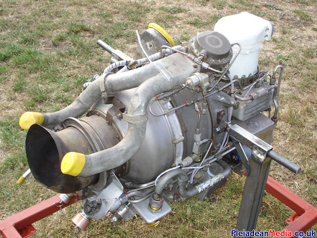
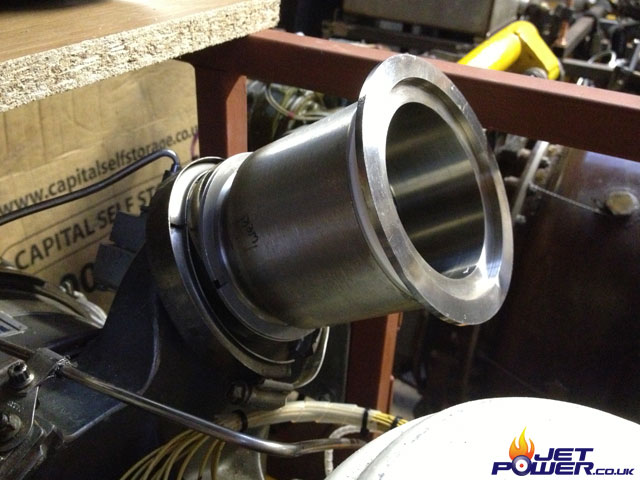
The air producer outlet port.
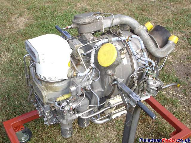
Overview.
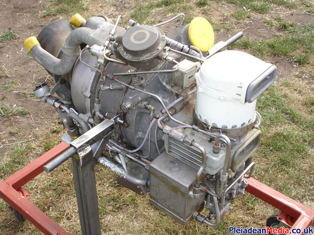
Oil quick release couplings.
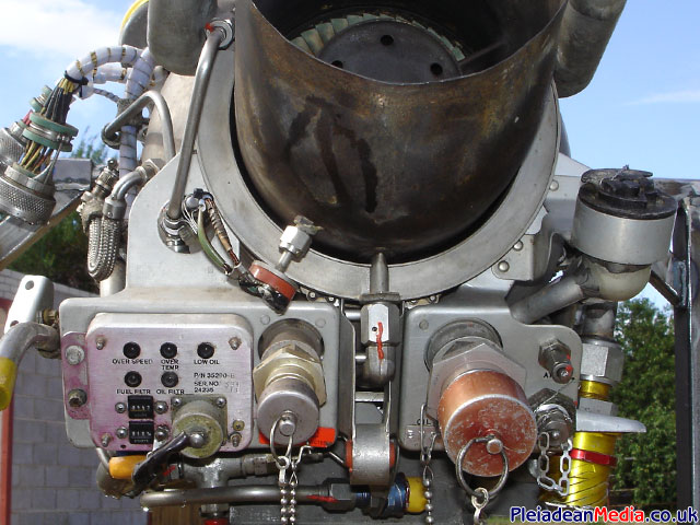
Connections and status panel.
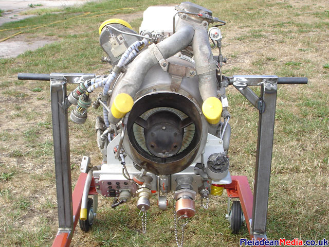
2nd stage turbine wheel, with the thermocouple just poking through on the bottom left.
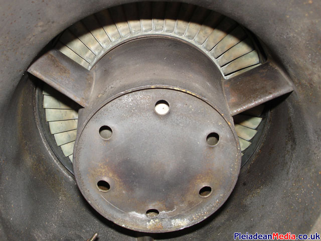
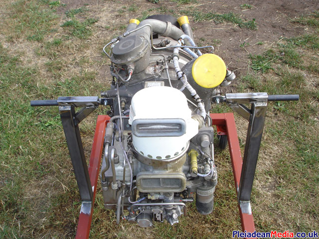
Underside. From the top left, oil tank, fuel and oil pumps with the filter housings on the right. The slit with the rotating cover is the air intake for the air producer compressor and the the open port below that is for the air intake for the engine itself. The connectors shown bottom left and right are the hydraulic starter inlet and outlet connectors.
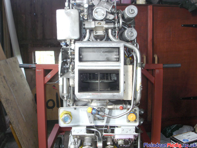
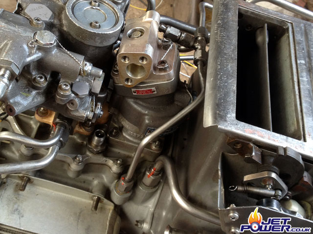
This picture shows the engine mounted upside down as now is the time to convert from hydraulic to electric start. You may notice that the start pipe has already been disconnected and it seems that its going to take a lot of work to get the starter off.
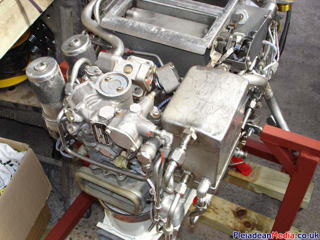
Oil tank removed for easer access and starter pipe taken off.
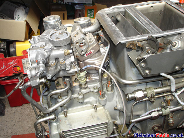
To remove the starter return pipe I had to take the fuel and oil filter bowls off along with loads of pipework, I just hope I can remember how it all goes back together again.
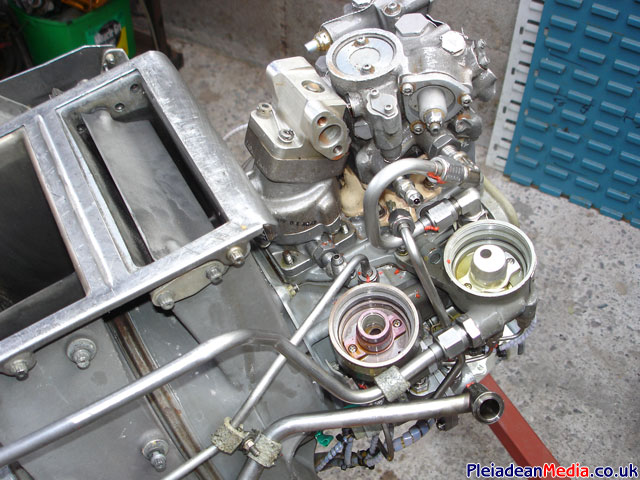
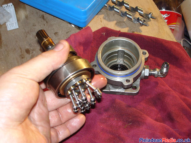
Hooorrrayyyy!!! Hydraulic starter removed, that was a fiddly job!
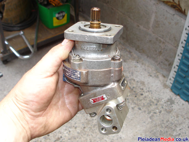
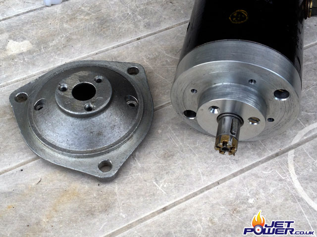
My idea is to use the base of the hydraulic starter as an interface between the electric starter and the engine. It seems a shame to cannibalise the starter, but this way I will already have the appropriate splined shaft ready to go, I will just need to machine up a mating flange.
This is where it went a bit weird, the engine was sold to Jon Starr, he played with it for a few years and now I have bought it back from him. I now have a real life use for it, it may not be powerful enough for my application, but that’s what testing is all about.
Jon managed to obtain a replacement hydraulic starter as I cannibalised the original one, he sourced it because he felt that an electric start unit was likely to very expensive and possibly unreliable, especially after the failure of a $400 motor he imported from the states, so why not restore it back to it’s original proven starting arrangement?
Saying that, I am prepared to give the electric start system another chance, if it fails I will probably complete the hydraulic starting system which Jon was in the process of doing when he sold me the engine. So as luck would have it, Ian recently picked up a series wound motor that may be just powerful enough to start the Williams, so I pinched it.
Jobs a Goodun.
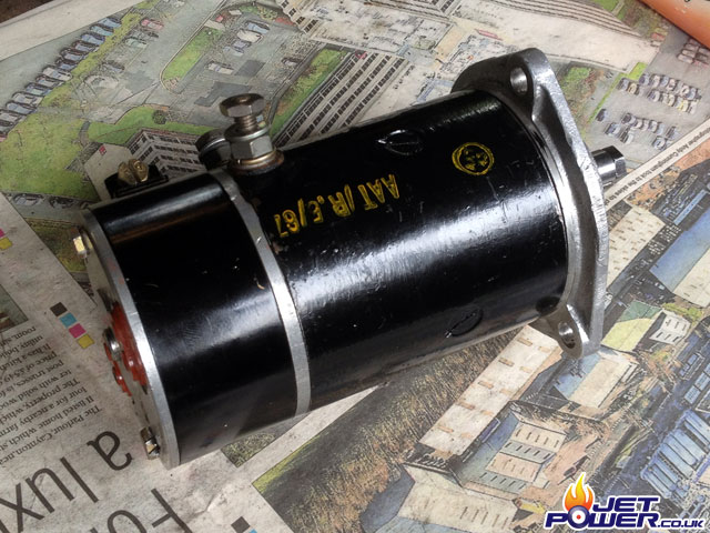
Hmm, that’s a pretty small keyway to take all the load that will be placed on it.
Pictured are the components that make the starter arrangement, from the left the original splined part of the hydraulic starter, then the spacer tube that Jon had made for his electric start system, followed by the drive spline which fits over the motor spindle.
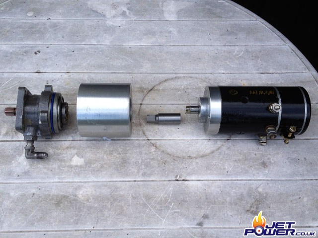
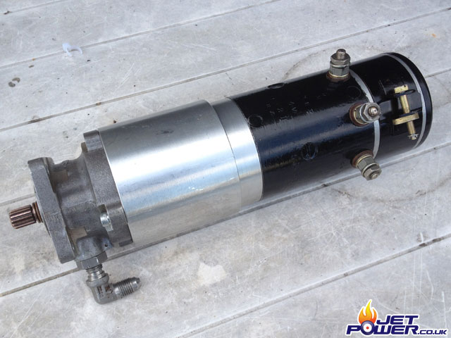
Hey Presto, a complete start unit, but will it be powerful enough?
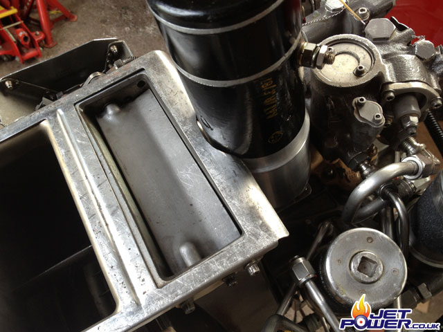
And it would be a decent project if the motor didn’t foul on the intake plate now would it! Fortunately the plate is made from .5mm stainless, so cutting a section out for the starter was easy, saying that every time something goes well, something else doesn’t, I wonder what it will be?
I have now modified the wiring loom and tried to colour code the various devices attached to the WR27, this way I feel more confident about where the wires are going and what they do.
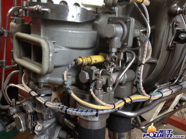
The built in generator is now no longer going to be used for it’s intended purpose, I will however take a tap from the coil to electronically obtain the engines RPM, at 100% RPM should equate to 600Hz.
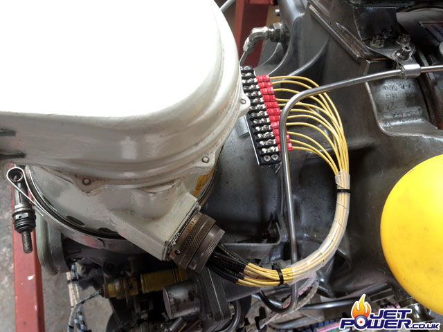
I have removed the original control/ junction box and replaced it with a die cast box, a QR Bicc or QM connector will be used to attach the control panels cables.
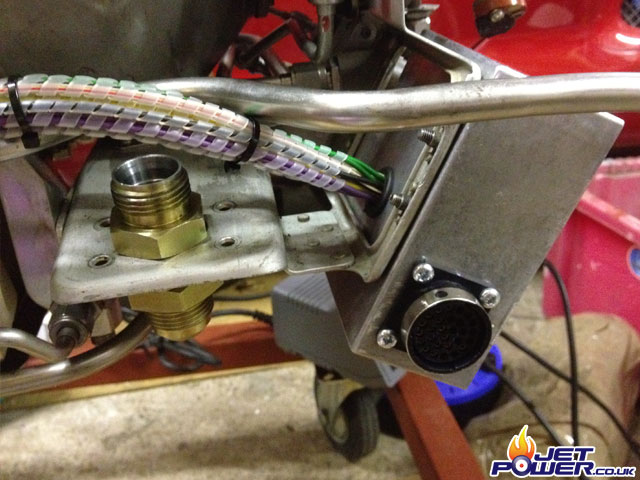
As a way of soft starting the starter motor, I made use of a Kelly ESC, easily programmed and set to go from zero to full power over 4 seconds. However in real word testing I managed to obtain a higher RPM without it, only a couple of percent, but every bit of power is required to start this engine with an electric starter motor.
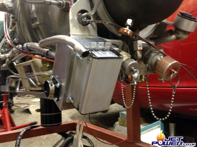
The control panel is made from 4mm aluminium and has been laser cut, the profile is designed to fit inside a Pelican case.
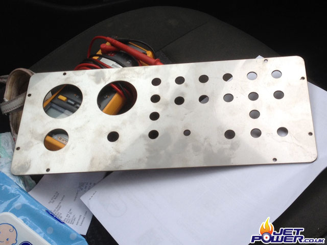
THe basic panel with components added, the wiring at the rear is the next job.
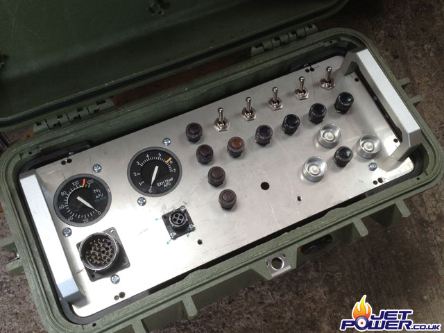
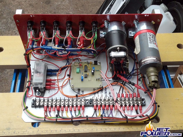
Wiring completed. To cut a long story short.
Latching starter relay with electronic cut out at 40%RPM, electronic RPM board with cut out (thanks to Ian) and alternating on/ off ADV using a relay. ADV energised with either Wander Lead, Mom Push or Latching Toggle Switch.
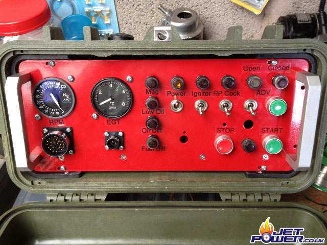
One completed Williams WR27-1 Control Panel.
The Mk1 starter kind of worked, but it’s neck was being ringed and it’s life span wasn’t going to be long. Thus back to the drawing board and a search for another more appropriate starter that will do the job. I found this starter on eBay and after a LOT of time and effort, not to mention money a suitable adapter was made.
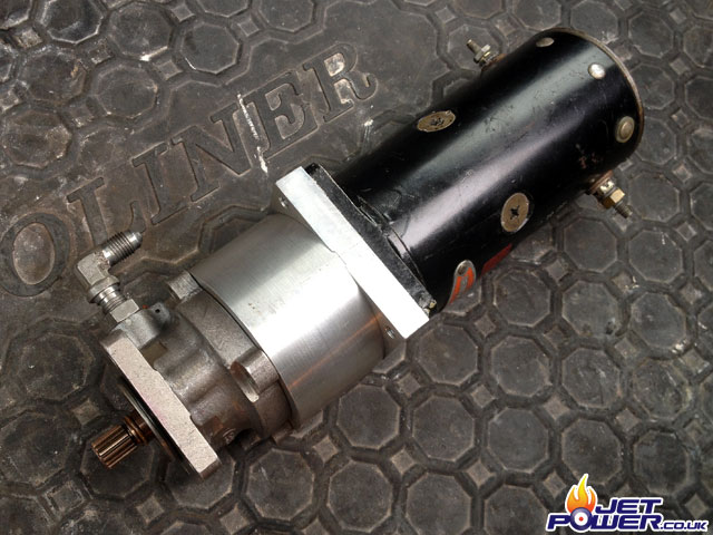
Pictured is the Mk2 starter fitted in place.
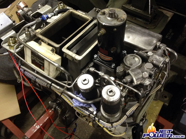
Now that things were coming along nicely, I decided to make a more suitable running frame for the Williams, dimensions may initially seem a little strange, but unavoidable as the air intakes are at the bottom of the engine.
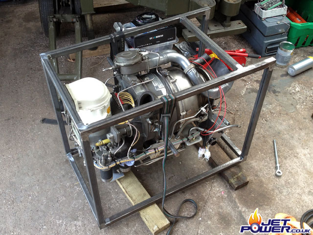
A coat of my old favorite Red Oxide paint and things seem to moving along quite nicely.
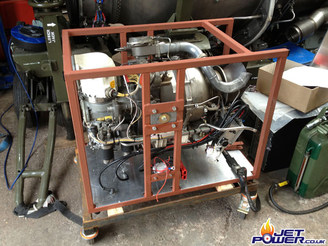
Another little detail was that a suitable adapter had to be made so the air delivery hose could be fitted, pictured is that adapter.
