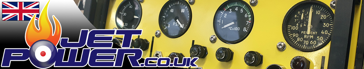
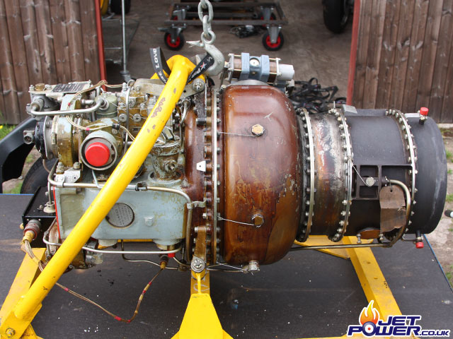
A bit of a road trip to the south of England to pick this beauty up.
A deal is done.
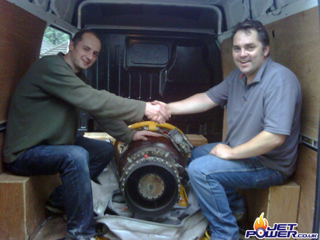
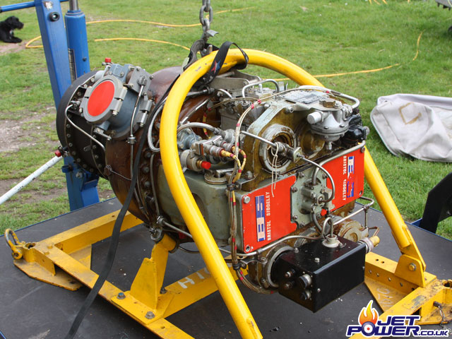
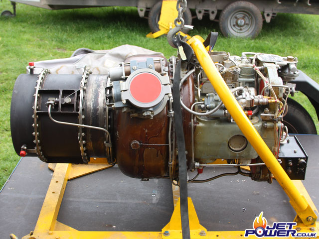
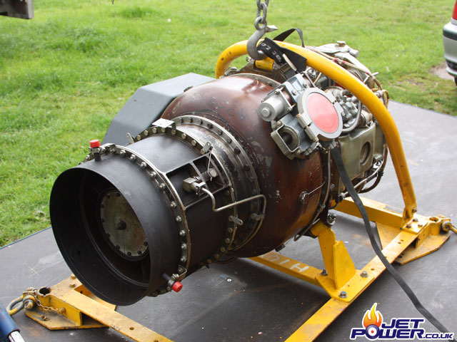
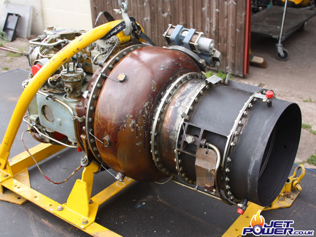
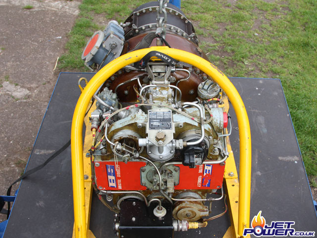
Bagged and tagged.
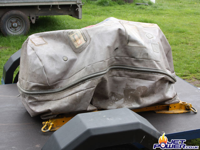
No paperwork, but I believe this was a rest zero hour unit.
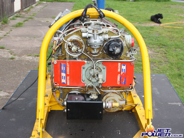
Now that compressor looks like new to me.
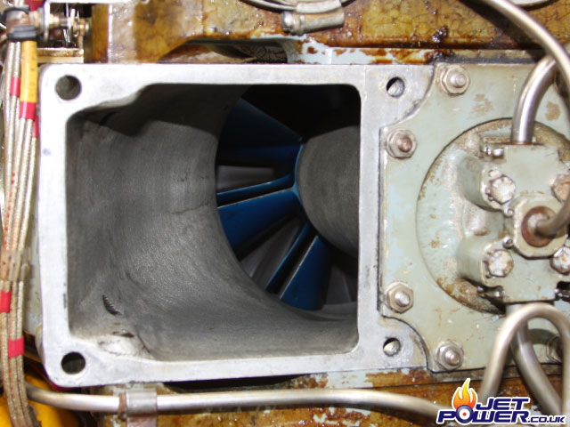
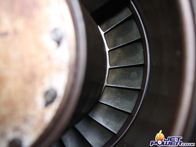
Turbine wheel looks good to!
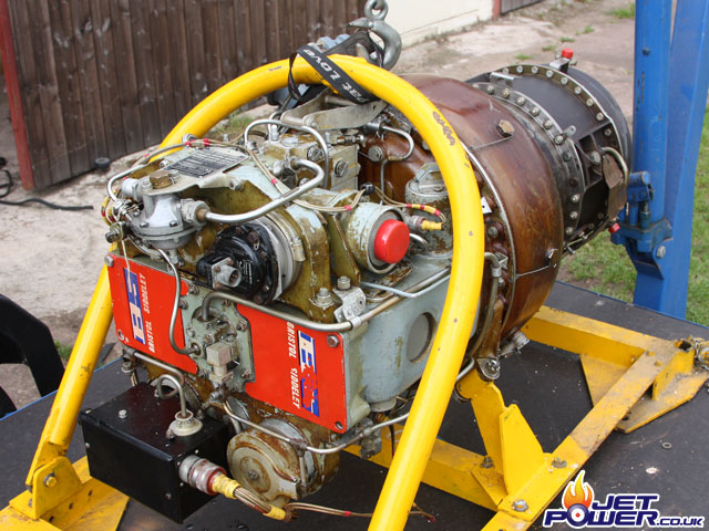
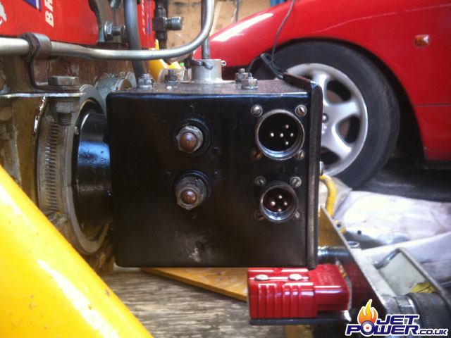
Electrical Control / Junction Box side view, the starter solenoid connectors are visible to the left as well as the engine control panel connector (upper) and the remote (usually aircraft) air producer connector (lower).
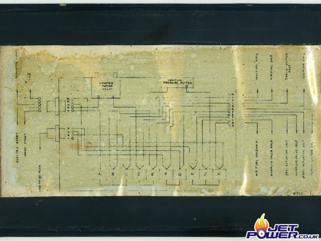
The cover of the junction box has a barley visible wiring diagram glued to it’s inner face.
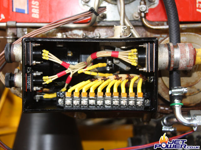
A view of the Electrical Control / Junction Box with the lid removed, the starter solenoid is to the left (hard to see) and the gas pressure switch is to the upper right hand side.
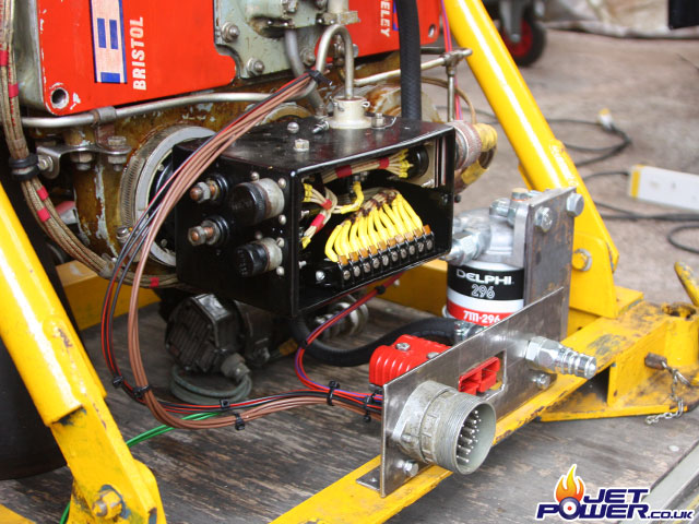
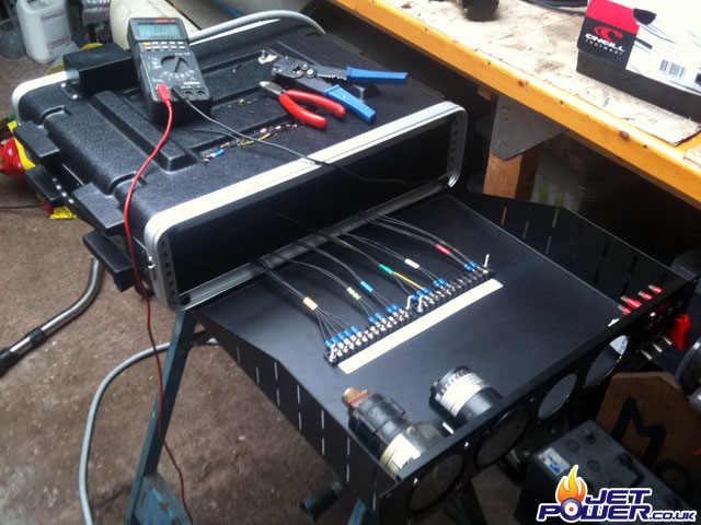
Now to make a basic I/O panel, all of the Palouste’s external control wiring will be soldered in to a large multi pole connector, power will be supplied via an Anderson 24Volt connector and finally fuel through a hydraulic 3/8 quick release fitting.
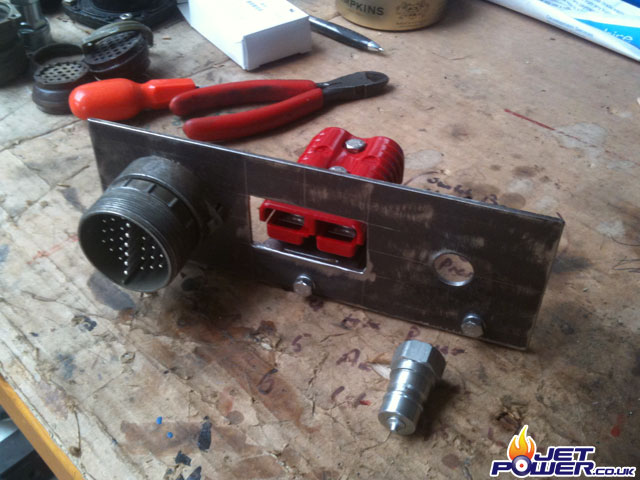
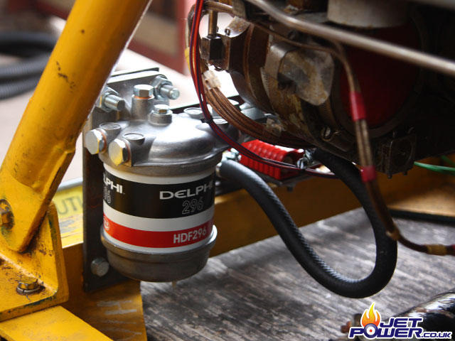
Again I’m using a tried and test ‘Lucas CAV’ type fuel filter assembly.
The start of the wiring, now just waiting for the old style ‘Breeze’ connectors to turn up from Servo, £100 just on connectors, not a cheap hobby.
I have now redrawn the engine side wiring diagram and also added a switched earth connection to previously unused pin D, this will be connected to an Indicator on the control panel to show the status of the air pressure switch. Also added but not shown on the diagram are EMF reduction diodes, these reduce electrical contact damage caused by the solenoids.
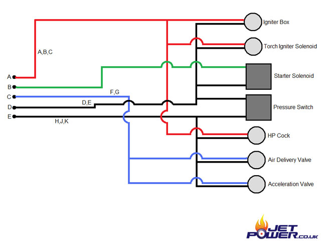
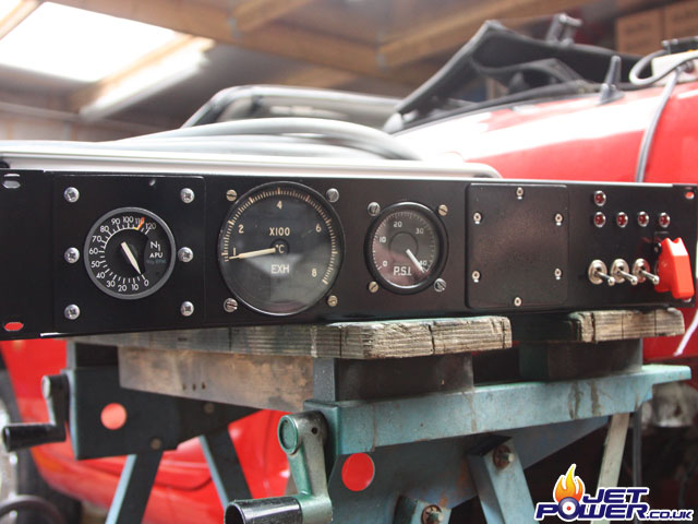
Basic control panel wiring diagram.
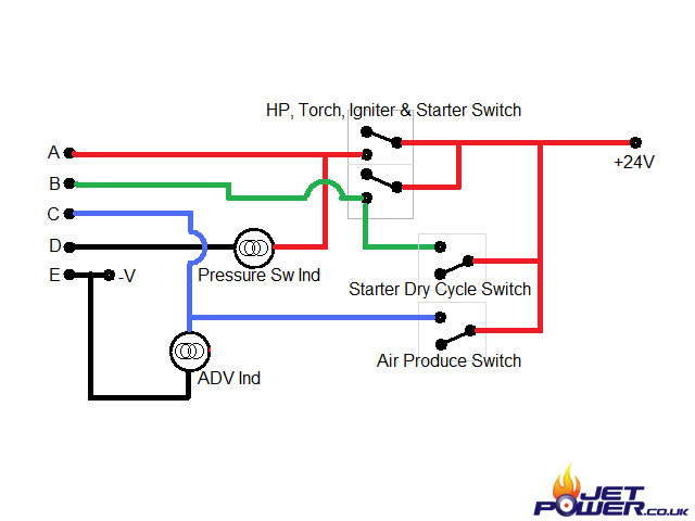
L to R. RPM, EGT, space for Oil PSI, Ammeter, run On/Off Sw & Ind, Air Pressure Sw Ind (above), Dry Cycle Sw & Ind, ADV Sw & Ind, Master Power & Ind.
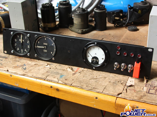
Yet again I am using a 2U ABS flight case as the control box enclosure, with matching faceplate and tray.
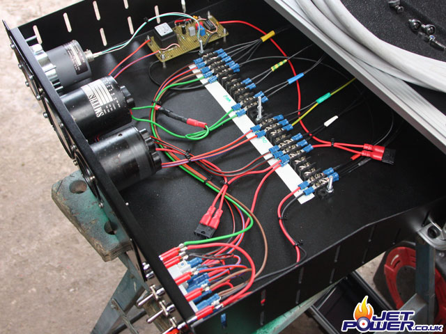
It turns out that the RPM gauge that I have is faulty so it has been replaced with an DC10 APU gauge, to get it to work correctly Ian has kindly made me an interface circuit that sorts this issue out, the circuit is pictured upper centre.
Updated front view of the control panel.
Successful first run.
Early shutdown as engine went out of parameter, after a checkout a faulty air pressure switch was identified and replaced.
Good run, though a leaking fuel pipe was noticed during the run.