This is my beloved Landrover Lightweight, its has a 2 1/4 litre petrol engine which isn’t the most economical or tuned engine partly due to the old style distributor ignition system. I have decided to upgrade the ignition to a programmable system using parts that are widely available, mainly from ford cars and a ECU kit imported from America.
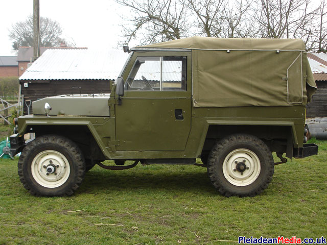
Here she is ‘Lucy’ the Lightweight (air portable) Landrover. This is the model that was thrown out of aero planes and transported by helicopter.

In the winter she has a hard top on, but when the summer comes around this is swapped for the soft top.
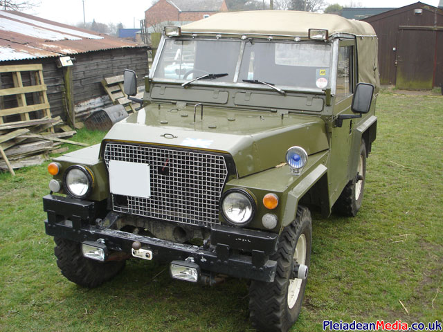
At some point I am going to replace the fog lights for something more appropriate.
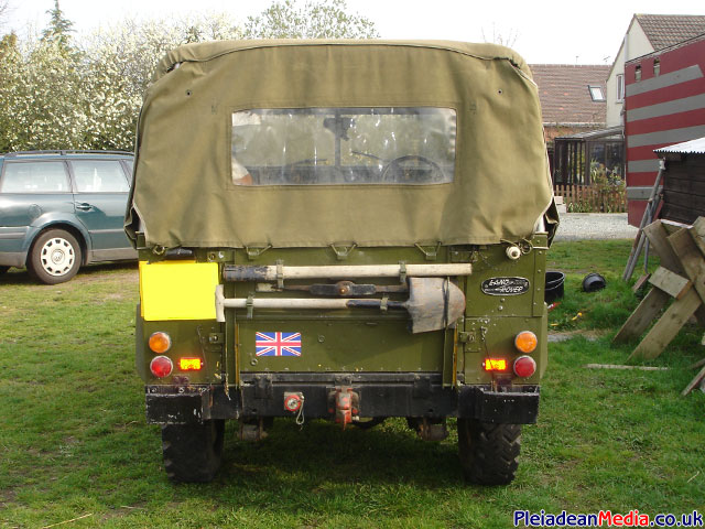
Rear view, funky pickaxe and shovel.
Right then, a basic overview of what I have to do for this modification. Firstly being a ‘landy’ the wiring (all of it) isn’t the best, this will be tidied up.
The distributor will be replaced by a ford edis4, an electronic module which will manage the sparks, and can be controlled by a programmable controller.
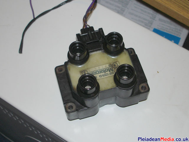
The old coil will be replaced with a ford 4 cyclinder coil pack, typically from a fiesta or escort, this will be controlled by the edis4 module.
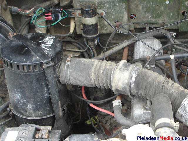
If you look to the left of the fuel solenoid you can just see a plastic cover which seals an opening directly to the manifold, this will be where I shall tap in to, to get the ‘MAP’ manifold absolute pressure reading.
The way the new system will work is by attaching a timing gear to the main crank pulley, then a sensor will read where the crank is positioned at any given point.
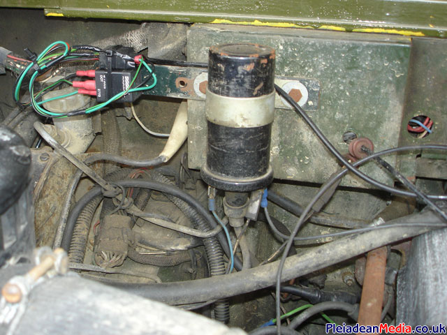
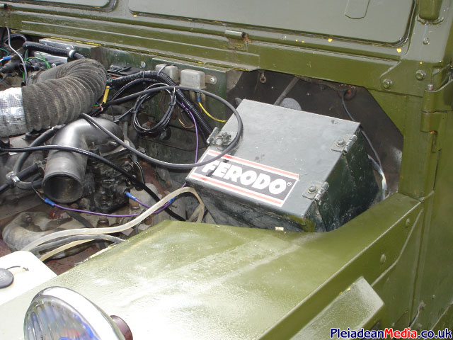
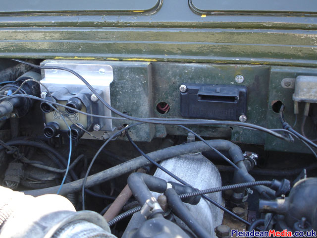
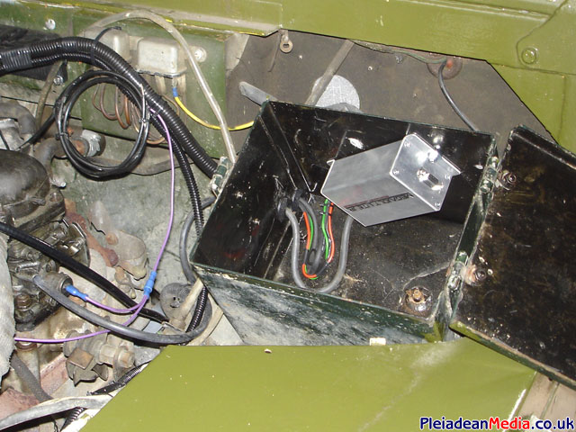
And finally, this is where I will fit the programmable ignition controller, in the ferodo box under the bonnet. As the unit is not waterproof and this is a landrover, I guess this is where its going to stay the dryest.
Now for some pictures of the parts that are required for the conversion. You can either get the bits from scrap cars or sellers on ebay.
- Ford Edis4 Module
- Ford Wasted Spark Coil Pack.
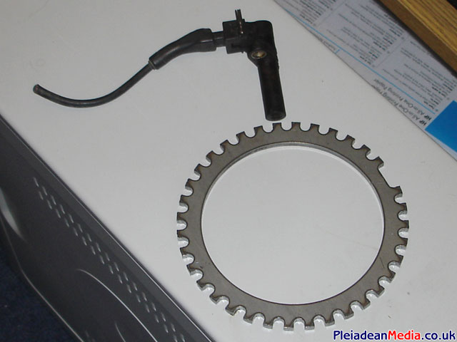
- Trigger Wheel & Ford Pickup Sensor.
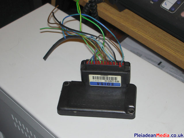
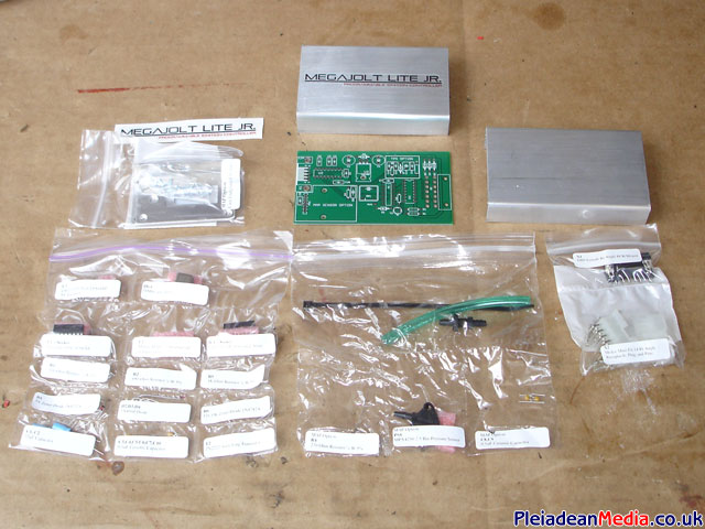
Brent Picasso’s Megajolt Programmable Controller.
All the wiring diagrams are on Brent’s website and there is also a very handy forum.
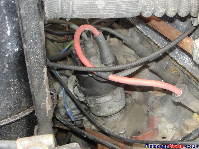
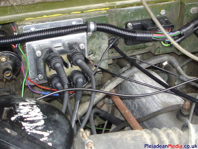
Now for the assembly bit. First to make a bracket that will fix the coil pack nicely to the landrover firewall/ bulkhead.
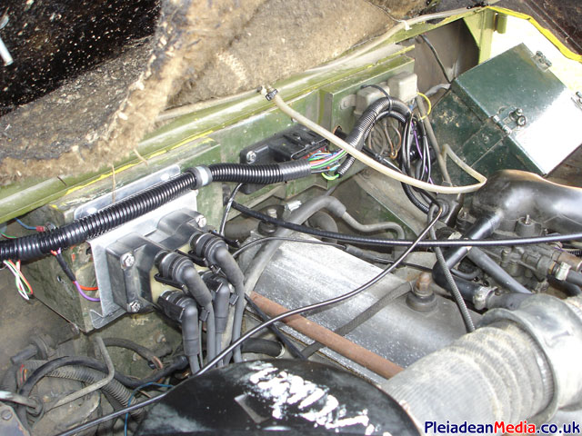
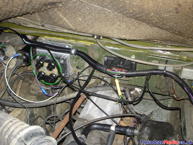
Coil pack now fixed in place. The next step is to attach the edis4 module to the bulkhead (as shown).
This shows the start of the wiring loom, its in its basic form at the moment as most of the connections will need to be made when in place.
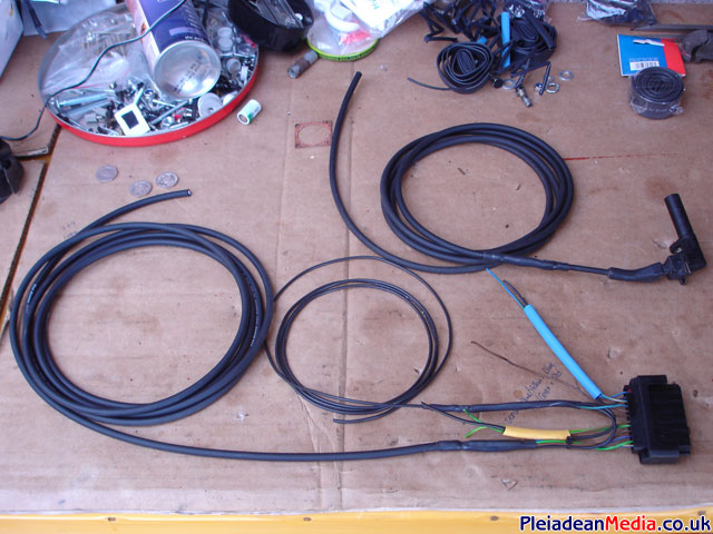
Wiring loom attached and covered in flexible conduit for wear protection, it also helps make the wiring under the bonnet look neater.
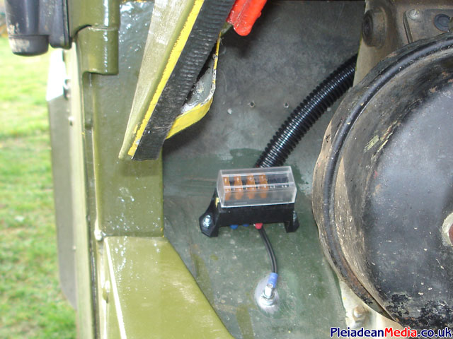
Fuse holder fixed. The feed comes from the supply from the ignition key which powered the original coil. I have four fuses, one for each of the main components and the gear shift light. Its also worth noting that all the negatives must bond to the chassis at the same point.
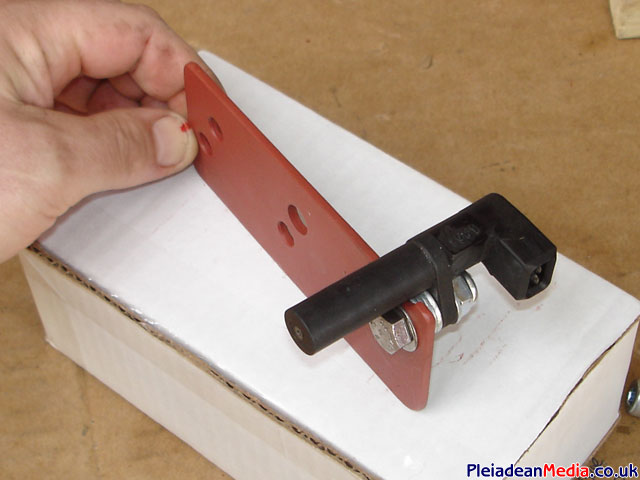
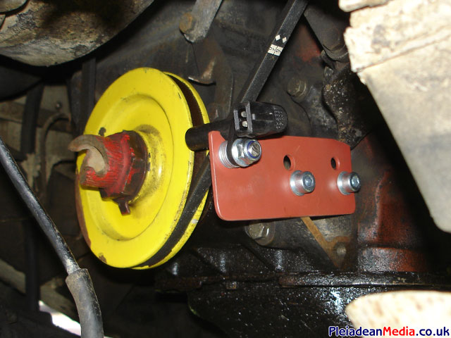
This is the bracket that will pick up the pulses from the trigger wheel, every engine seems to be different, but this is the only way I can see mine working. It took a few attempts to get this final version.
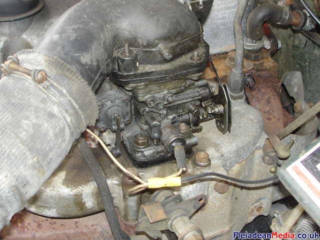
I have now started to assemble the megajolt kit. Its a straight forward kit to build and comprehensive assembly instructions can be found on the manufacturers website. There are 2 options with the kit, 1 is that you can have a throttle position sensor or 2 you can have a inlet manifold pressure sensor, I opted for the latter when ordering.
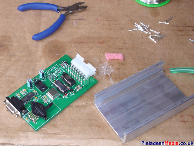
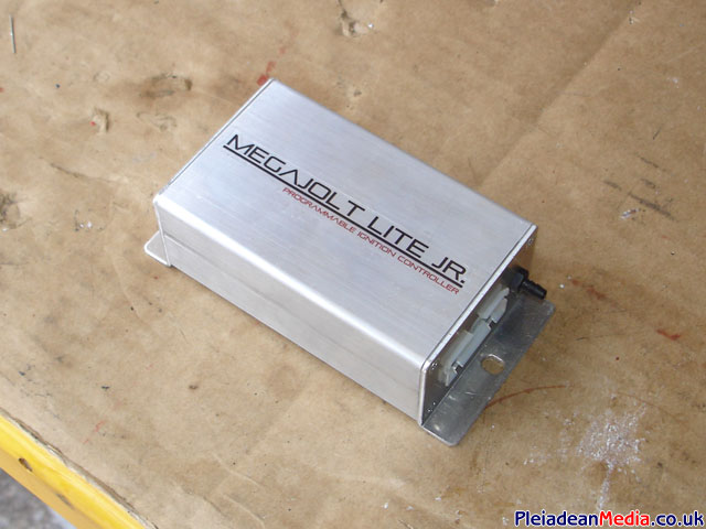
Megajolt programmable controller completed.
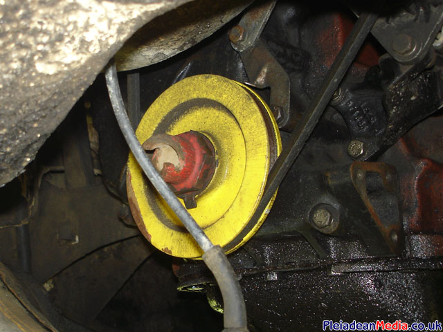
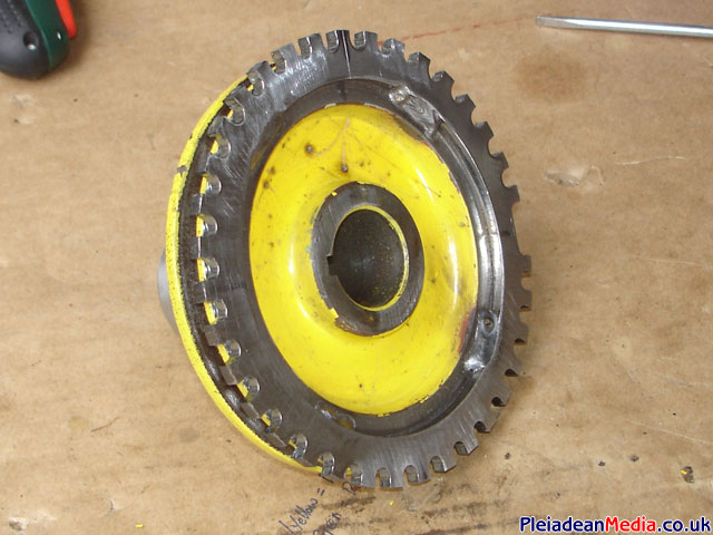
Next the fiddly bit, I bolted the pick up sensor on to the engine block and made sure that the sensor was square on to the center of the pulley, then using markings that were on the block I made sure the pulley was rotated to TDC (Thanks Robert for the advice) and then made appropriate scribes of the positions.
2 seconds later the pulley was off and the front face sanded down so that the trigger wheel could be welded in place, I was careful not to sand away the sensor position.
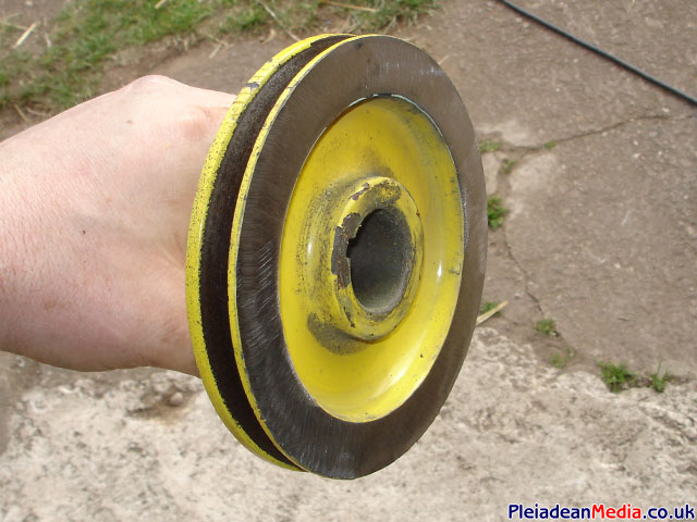
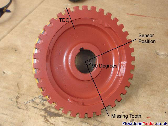
I then proceeded to weld in four places the trigger wheel which was carefully centered on the pulley, the missing tooth part of the wheel was located 90 degrees clockwise away from the sensor scribe point.
A coat of paint and the jobs a goodun.
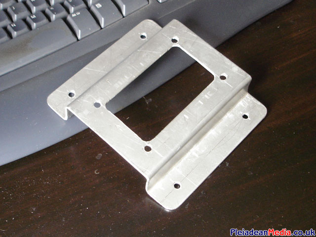
Now to fix the megajolt in to its housing, the unit itself isn’t in fact waterproof, and the housing under the bonnet isn’t perfect, but I would say it was the dryest part of the landrover in usual circumstances.
A new set of ford jump leads cut down so that they are a perfect fit from the coil pack.
Shift light (LED) cluster fitted, not in an ideal place, but I felt it would be best to use one of the existing holes rather than make a new one. I’m sure I will be able to manage.
Completed, jobs a goodun, now for some programming.