Previous Page (1)
Hawker Hunter T7 on Display at RAF Cosford.
(Cold War Hanger above the Avro Vulcan)

17 Years Later
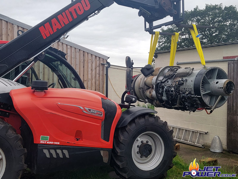
Alan’s the chap I sold the Avon to so many years ago and it has stayed as a curiosity in his MOT Garage in Leeds since then. Apart from being dusty, the condition is the same as when it was sold. Thanks have to be given to Alan and his lads for getting the 122 safely loaded on to the trailer, at nearly 1.5 tons it would have been a struggle without them.
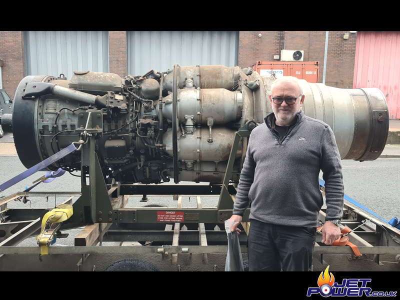
Care was taken strapping the Avon down with a journey time of just under 2 1/2 hours. My mate Nic Storey, a fellow Aviation enthusiast came along for a ride and was a great navigator in and around Leeds.
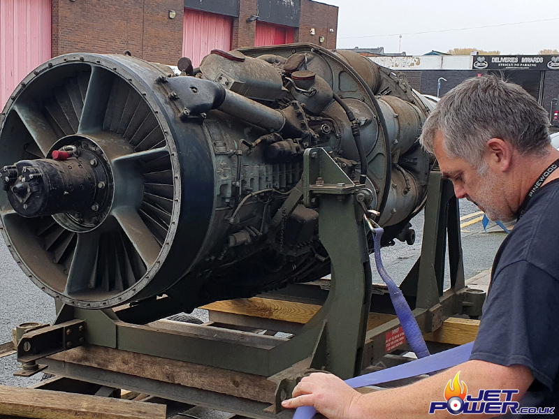
And finally back at home, time to get it off the trailer and give it a good clean, though the weather coming through Manchester gave it a pre-wash. 😉
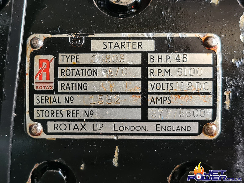
So now the engine has had a basic clean to remove the dirt and a quick spray of WD40 in the nooks and crannies. As a finally test of the day and as I had never done this when I pre-owned the engine I put 12 VDC in to the starter to check it still worked and to confirm the correct rotation.
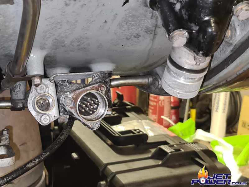
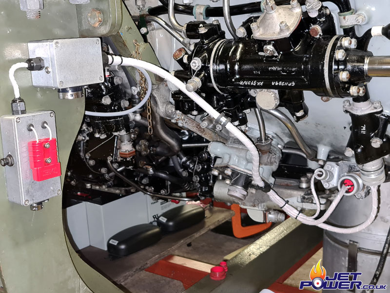
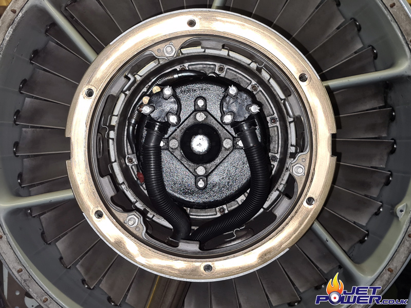
So it begins. As usual I am going to start with the electronics, 3 connectors feed in to the engine, with EGT, HEIU & Starter as additionals. The connectors are of the Plessey Breeze type and are getting harder to source by the day, the left hand 2 pole connector plug I found in my workshop, the right hand 12 pole was found during a rummage at GB Air Spares, the centre connector was going to be a problem… The flash of the camera makes the connector environment look a bit rough, but in reality it’s pretty tidy down there.
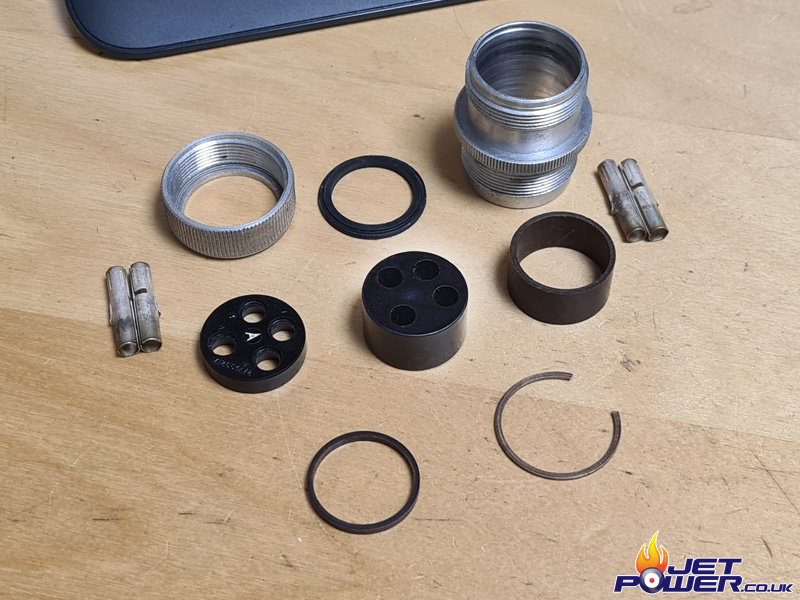
So after time wasted trying to find a suitable connector, I stumbled upon an unused 4 pole connector that had the correct bore and thread, it occurred to me that I could 3D Print the required components to the sizes required by the 12 pole, also I would need some contacts, so through eBay I sourced a 24 pole connector that would act as a donor.
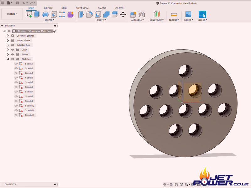
Connector profile drawn up in CAD, then printed using my Ultimaker.
And Hey Presto, 1 x 12 Way Breeze Connector.
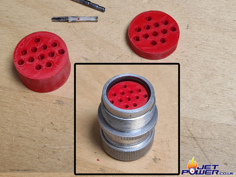
That’s the Engine side wiring interface completed.
I don’t really like disconnecting breeze connectors regularly which would be something that would happen as the engine is only going to be a mobile ground running unit. So to avoid these connect/ disconnects I have added a single more reliable Cannon ITT QM Connector on to the underside of the top aluminium enclosure and run the wires back to it from the engine. The left hand enclosure houses a 5 amp circuit breaker with an Anderson power connector on top. Also on the bottom is a QM which will connect to the electronic speed controller for the starter motor operation.
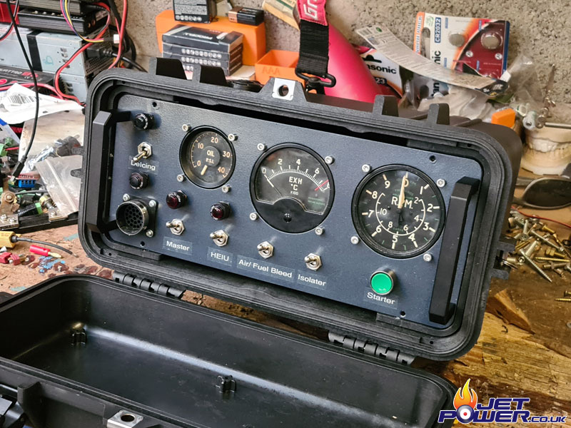
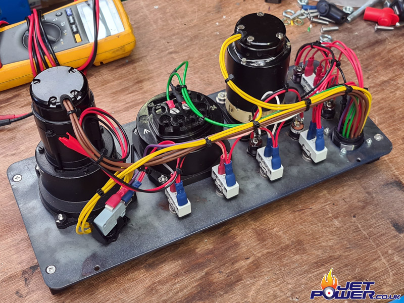
Keeping in line with my general electronic control panel design, here is the current configuration of the Avon panel.
From the left.
# Anti Icing Switch & Limit Indicators (Gate Valve Actuator)
# 28 Way Cannon ITT QM Electrical Connector
# Oil PSI Indicator (26 VAC 400 Cyc)
# Master Power Switch & Indicator (28 VDC)
# HEIU
# Exhaust Gas Temperature Indicator
# Air & Fuel Bleed Solenoid
# Fuel Pump Isolation Solenoid
# Tachometer Indicator
# Manual Starter Motor Switch
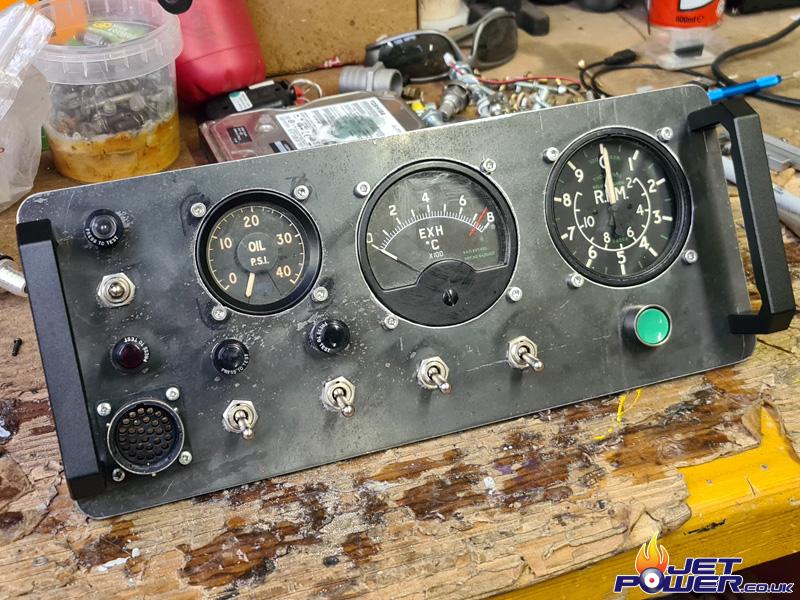
I Powder Coated the Control Panel “Gun Metal”, I think it looks pretty good.
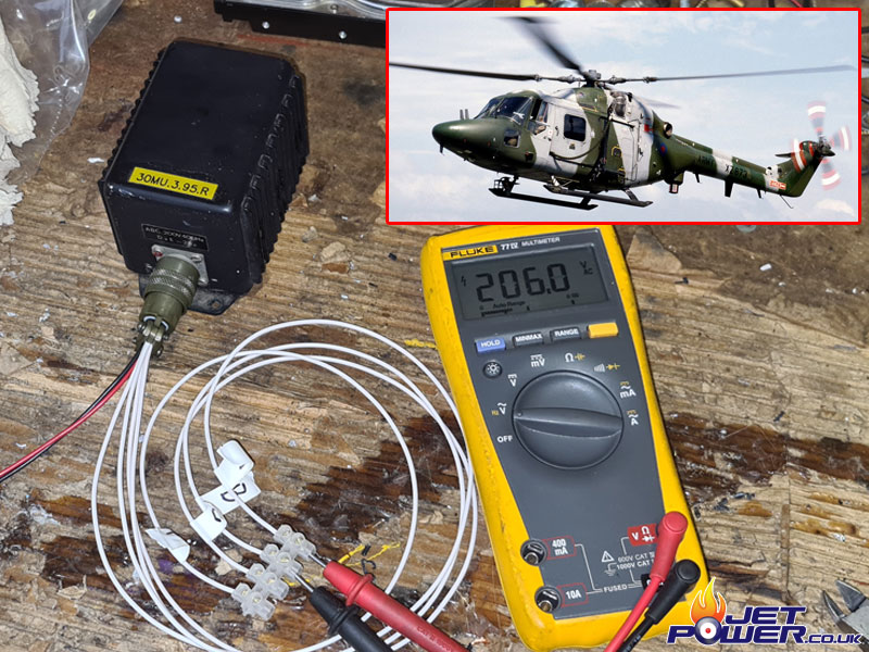
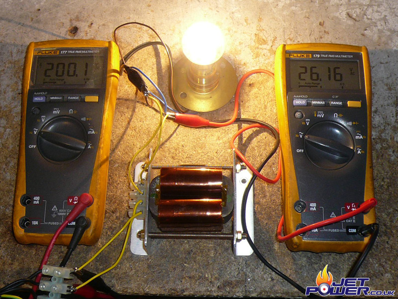
The Avon’s oil pressure gauge and sender work on 26VAC @ 400 Cycles, thus a Static Inverter has to be utilized. The one I am using once belonged to Lynx XZ673 pictured on the inset, it gives me 200 VAC so I have yet to find a way of getting it down to 26 VAC.
The spotters of you may find this info useful:
NATO Stock No: 6130-14-3010421
Part Number: TSG 420-201
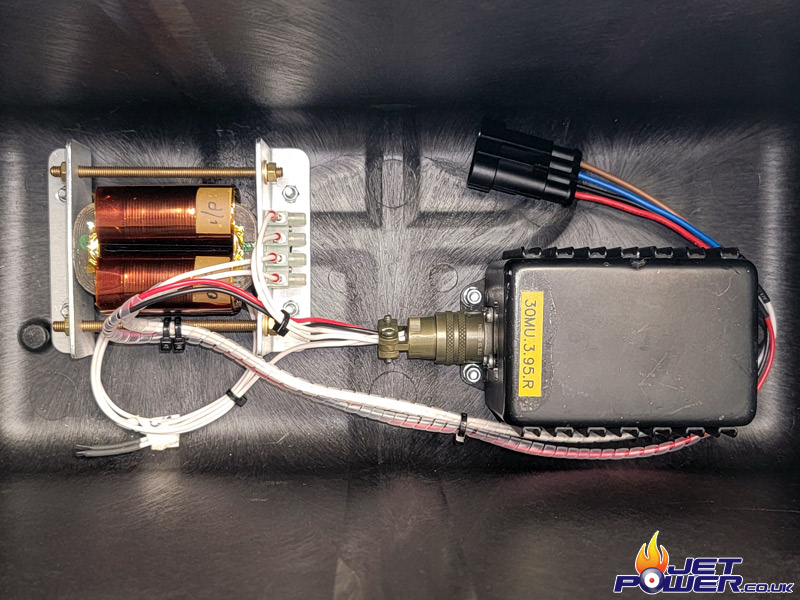
Wiring complete on the control panel, just need to add the Inverter and 200 VAC to 26 VAC Tranny to power the Oil PSI Gauge..
Custom 200 VAC to 26 VAC Transformer courtesy of Paul Bennett.
Transformer and Inverter fitted in to the base of the Peli Control Panel Case, connection is via a 4 way automotive connector.
I am in a fortunate position to have an electric starter for the Avon, a very hard to find item and a replacement will be almost impossible to source. So with that said, I need to treat the starter with as much care as possible as other options for starting the Avon are extremely limited. The starter operates off 120 vdc and under normal conditions, puts out a max 45 BHP.
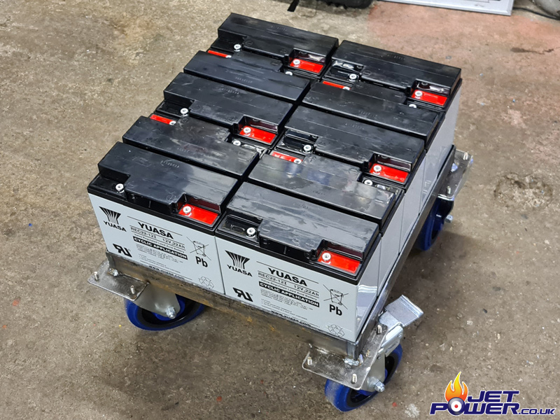
Now, arguably not ideal, but I have opted to use 10 x 22Ah Gel Batteries as the power source, using these I am likely to get only a handful of starts, but for now they will do as the budget to get this engine running has already been exceeded. I made a basic battery tray mounted on to castor wheels to help get the battery pack about as there is some weight in this package.
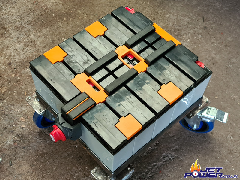
Using some copper strip that I had in the workshop I made the battery connection links and where possible covered them in heat shrink as 120 vdc could be fatal if touched, it’s actually a very scary voltage. To increase the safety of the pack, I also 3D Printed some covers which then fully covered any exposed connections. The DC Isolator half’s the packs voltage thus making the overall voltage lower and safer and is only to be engaged when there is zero load on the pack.
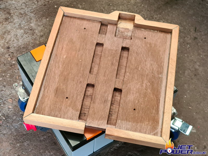
As I seem to have a fair bit of Oak lying around due to a recent house refurbishment, I made a lid to cover the top of the pack, with slots recessed in to it for the copper strips to sit comfortably in when it’s located in place.
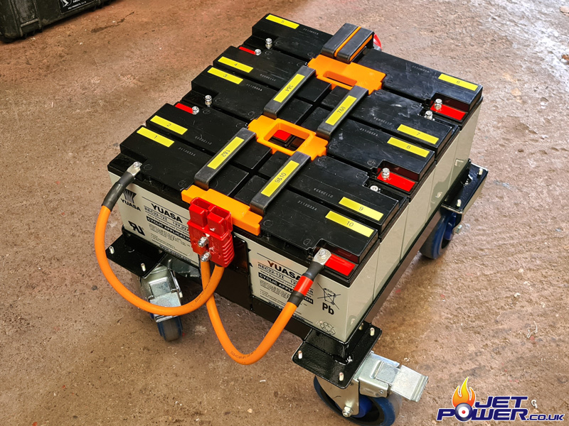
I would have used purple Anderson Connectors if they were available as they indicate 120 volts, but they were not, so I made use of some red ones (24vdc )which I had anyway. Batteries were numbered, as were the copper link bars.
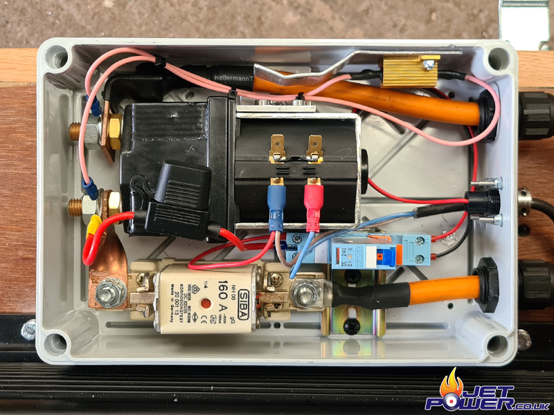
The white box contains the Controllers DC 160 Amp fuse and Isolation Contactor, again both safety features. There is also a 25W Soft Charge Resistor mounted across the Contactor to help preserve the life of the Controllers Capacitors when initially powering up. When the relay is activated by the control panel (28vdc), it closes the Contactor and turns the controllers outputs to on, powering the Starter.
For those spotters among you, yes I still have yet to add the EMF protection Diode.
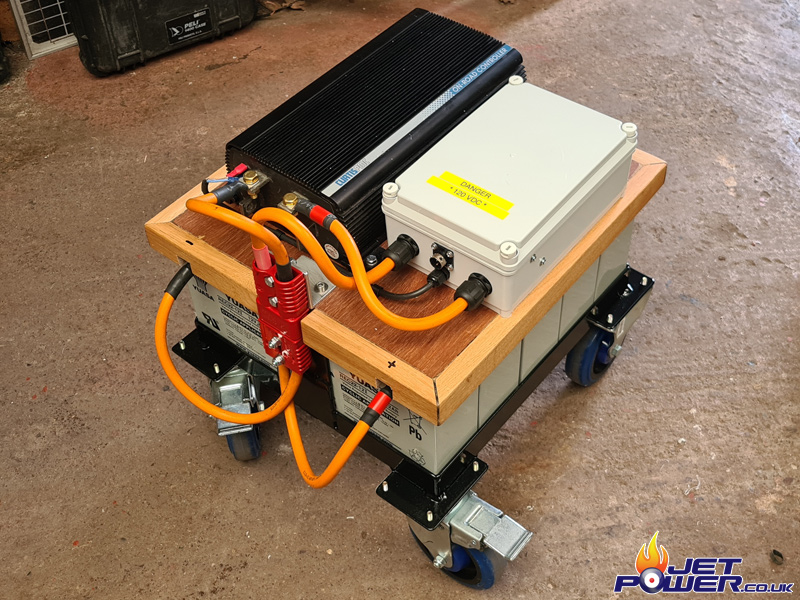
On top of the lid I have fixed a DC High Power EV Curtis Controller, this will act as a soft start for the Starter Motor helping to prolong its life, with it I can set the Max Amps and Acceleration Ramp when Starting. Also, you will now notice the placement of the Anderson Connector, when the wooden lid is removed to access the batteries for charging, disconnection of the power is also made making operation a bit safer. Leads from the pack to the starter have yet to be added.
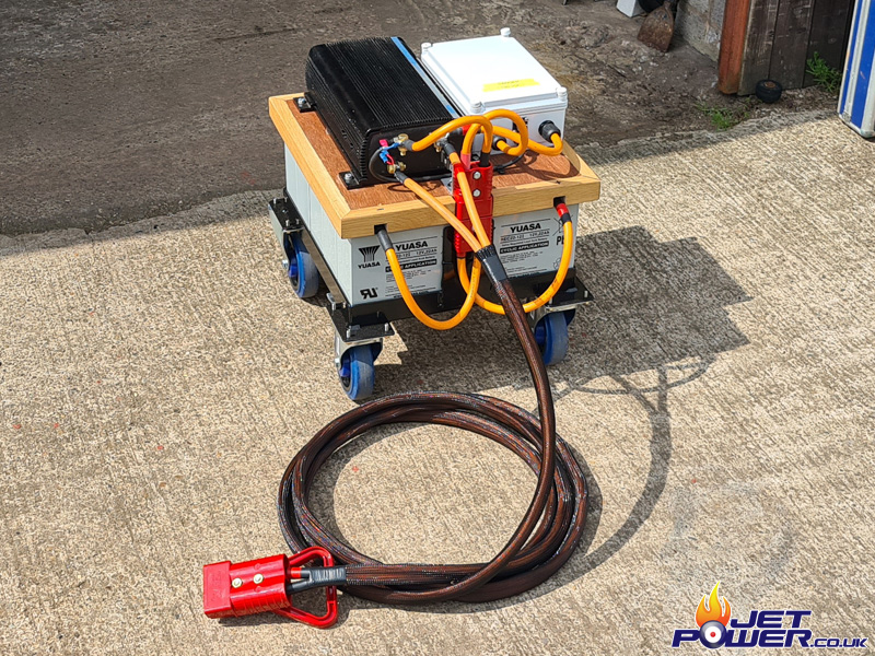
And it’s finished, 1 x 120 VDC Soft Start GPU
Originally this engine was cartridge start, I would have kept it that way if the cartridges were easily available, but they are not and are becoming a thing of rarity. The original cartridge bullet intake has no provision to get starter wires to the starter, so I sourced an appropriate diameter stainless tube and fabricated a bracket which I then attached to the engine, the starter wires will run safely inside of this out of harms way.
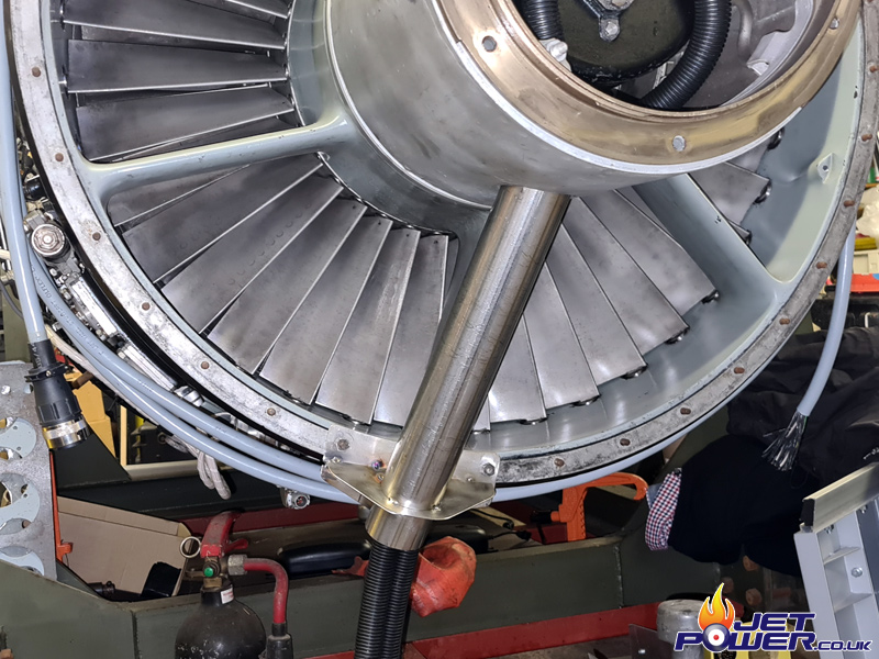
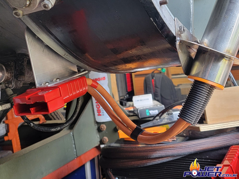
I get a bit scared of high DC voltages, so not only am I using double insulated power cable, its also running inside some protective flexible trunking. Termination of the stater wires can be seen below.
I 3D printed some cable spacers to insert in to the stainless tube to keep the wires nice and tidy inside of it and to avoid chaffing on the exit. Also I would have used violet Anderson connectors if they had been available, but I have had to make use of some red ones which I already had, these are normally assigned for 24 vdc operation. The connector is held in place using some aluminium angle bolted to the engines housing.
Now to move on to the Igniters and not for one moment did I think these would be in this poor condition, from an engine with only 30 hours on the clock and both sides were the same. Luckily for me though they did clean up ok, but I will be looking out for some replacements for sure.
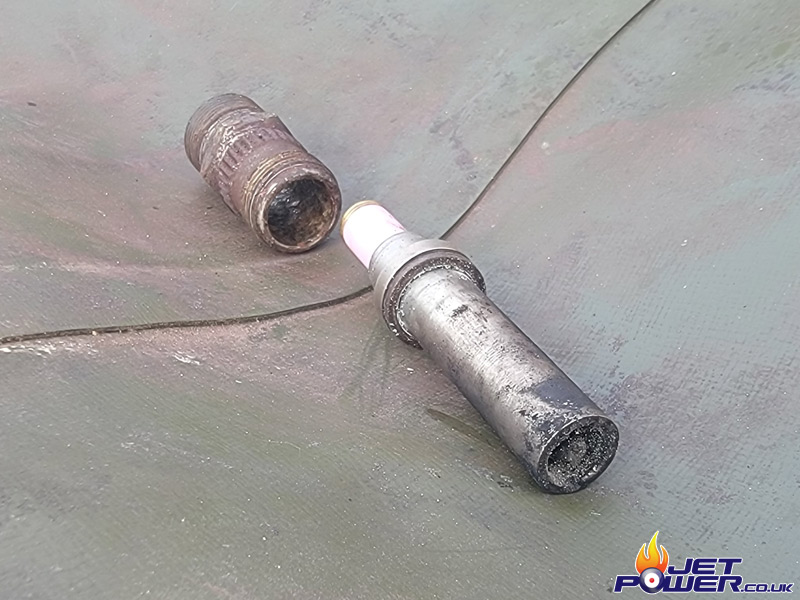
Now, another little shock, my HV leads ceramic insulation is to long and there is no way that I can get the ground surfaces of the lead and igniter to mate, so this is a new one to me, there must have been a lead with a shortened ceramic section specifically for this mark of Avon?
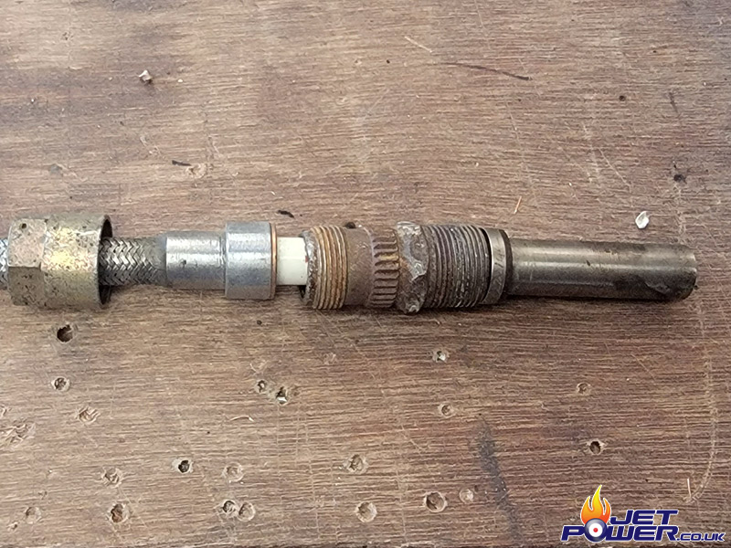
So my workaround is to space the igniter plugs out from the intermediate coupling with 4 copper washers, I found these in one of my drawers and they are almost a perfect fit, this gives me the required length to allow the lead to clamp correctly.
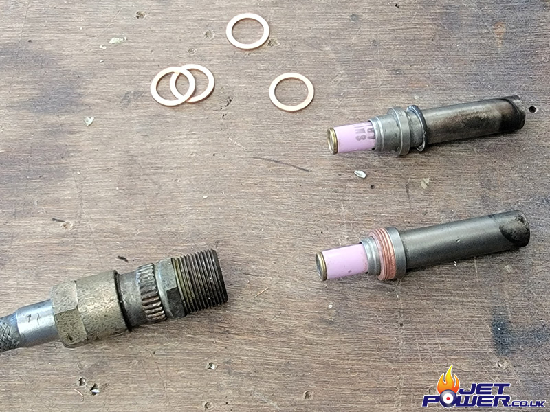
So it may protrude slightly out a bit further than I would have liked, but until another solution presents itself, this will be more than adaquate.
Now on to the Oil System.
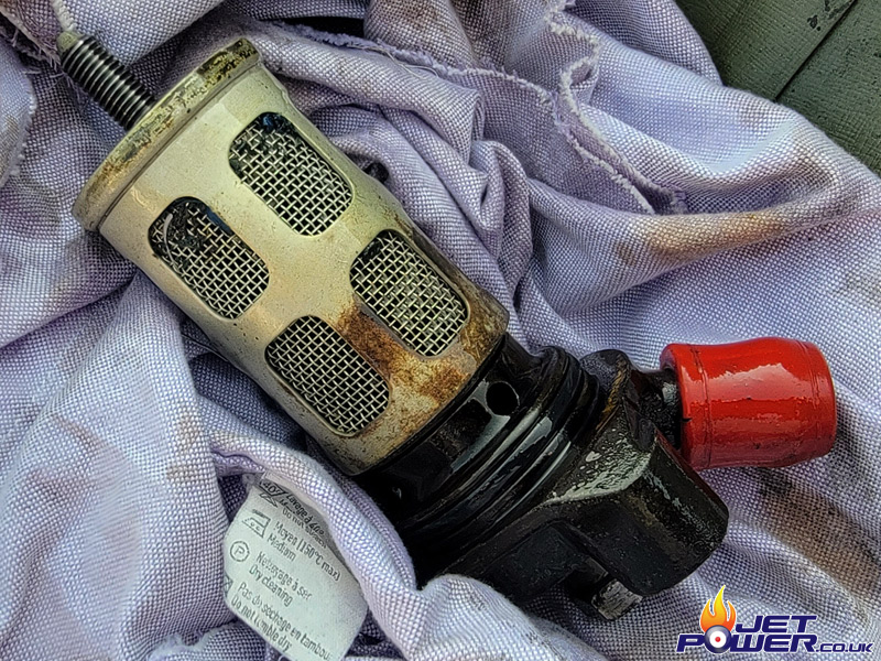
I removed the low pressure oil strainer from the under side of the engine and my first impressions were not that great. There appeared to be a cluster of blue metal fillings around the strainer and one shiny clip of aluminium that can be seen in the picture. So with some clean Kerosene I started to clean the filter out, it soon became apparent that the blue chips were in fact not metal, but bits of rubber or sealant which were squishy to the touch, not ideal but not that bad either.
I filled the Avon with the appropriate amount of Aeroshell 500, made a careful measurement, so that I can monitor its oil usage.
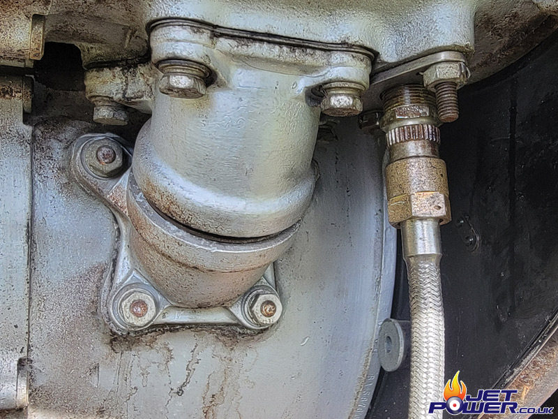
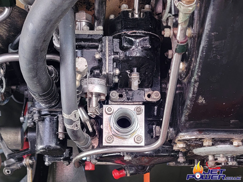
The fuel is fed to the lower part of the engine where the FCU is located. For transport the ‘two’ fuel inlet ports are blanked, this means for operation I will have to make an adapter. A piece of 8mm aluminium plate with a 1″ BSP thread tapped in to the centre will do the job nicely.
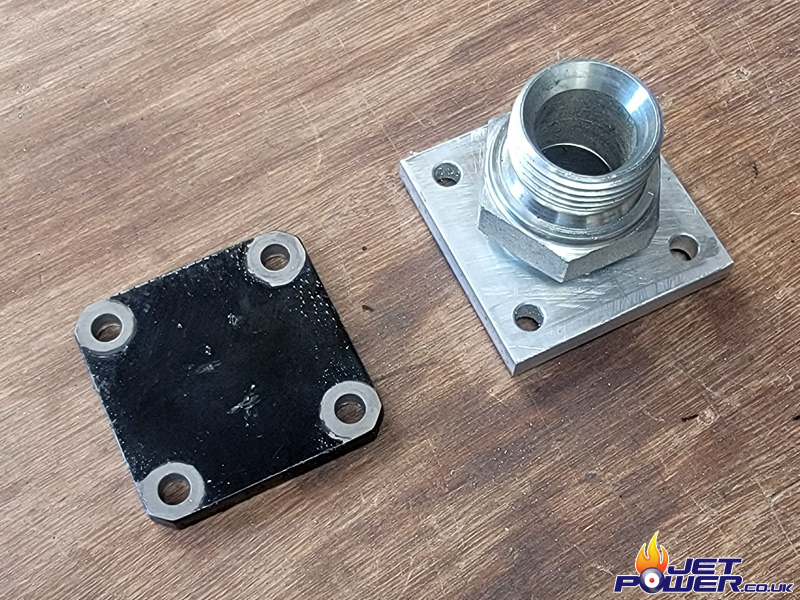
Fuel adapter inlet located in to place.
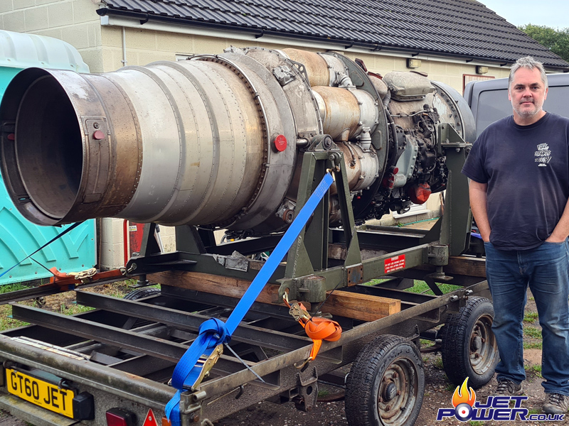
To progress further, I really need the engine to be on it’s running frame, which hasn’t been made yet. So I removed the Avon from it’s transport frame and carefully set it down on to the Avon’s built in rollers. With the Avon removed it will be a lot easier taking the transport frames measurements and transferring them across to the new frame.