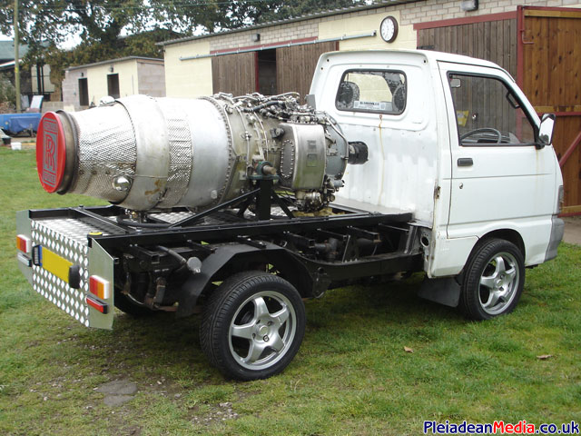
Now that the RR Viper is fully working, it had to be fitted to something, a Custom Daihatsu Hi-Jet Pick Up Truck in fact and why not?
Just picked the beast up.
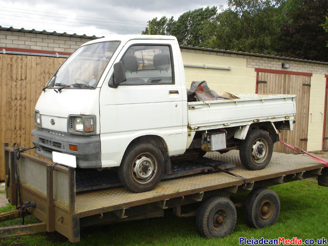
What a beauty, with a Viper on the back and a navy blue re-spray she’s going to look ace! (Probably).

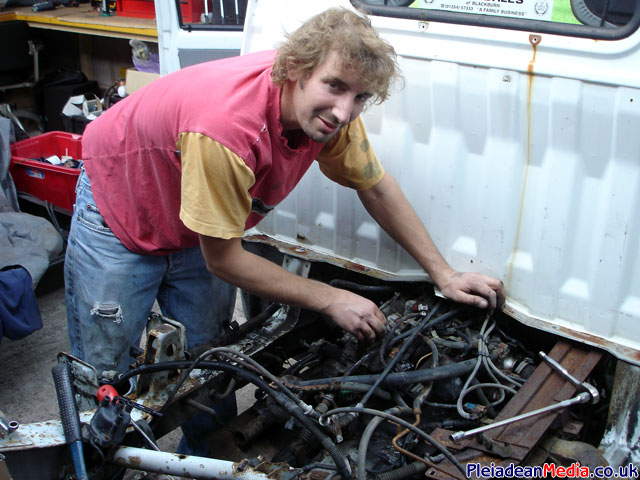
My old faithful mate Rob working on the engine of the Hi Jet. The Hi Jet was purchased with a suspected seized crank, but unfortunately we found it to be a lot worse than we anticipated.
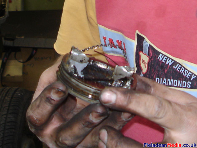
For example here is part of one of the pistons, at a guess this engines had a con-rod failure… Now we are off to the breakers yard to find a replacement engine.
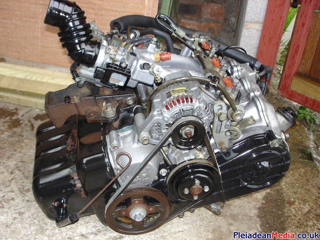
1 x Replacement Daihatsu Hi Jet Engine, purchased from CPI in Bridgnorth with 6 months guarantee and at a bargain price! Cheers lads.
Not a particularly flattering shot of the Hi Jet.
Fuel Tank, Exhaust, Engine & Gearbox removed and chassis made ready for a coat of paint.
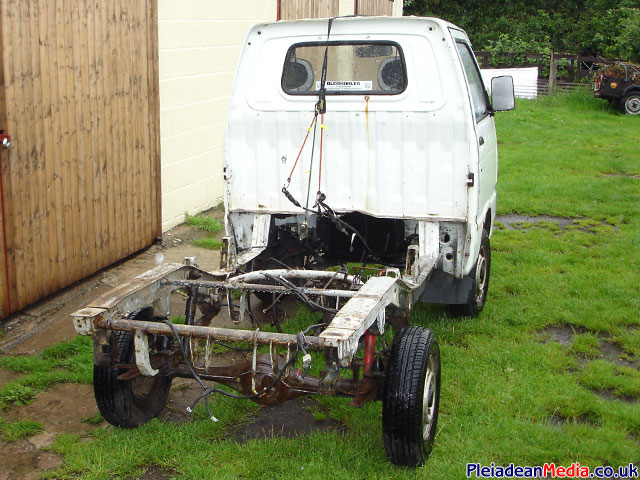
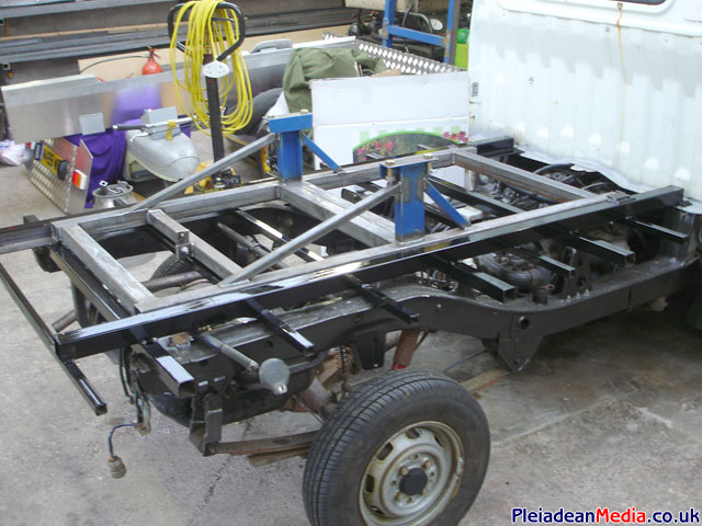
The chassis has now been painted black and the fuel tank etc put back on. We have also started the construction of the Viper quick release frame, this is going to have to be built as light as possible as the max load weight is only 3/4 tonne.
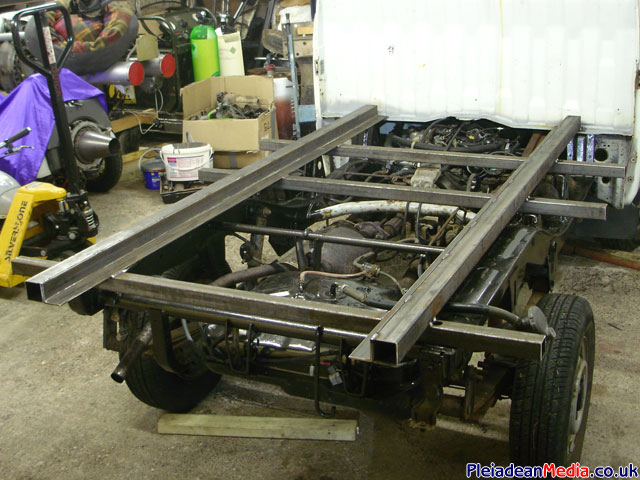
The Hi Jet support frame has now been finished and a coat of paint applied. The removable engine mounting frame is coming along slowly but nicely, this can be seen on the picture above.
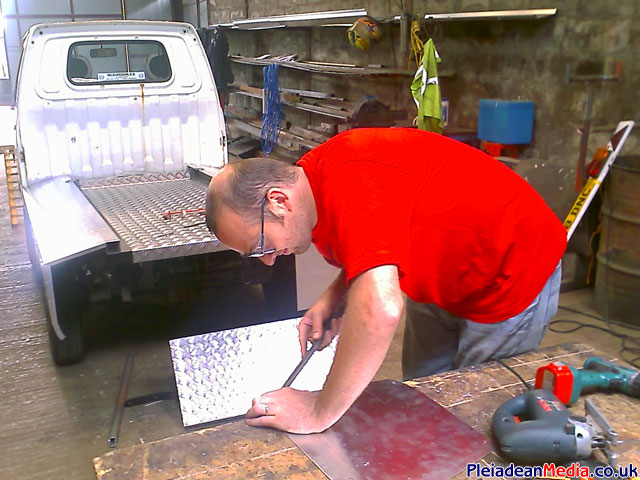
Time to get on and make the rear body, for this I will use 2mm plain & 2mm chequer aluminum plate. Pictured is Lord Anton D’ Bar at work in his dungeon workshop.
A view of the bodywork.
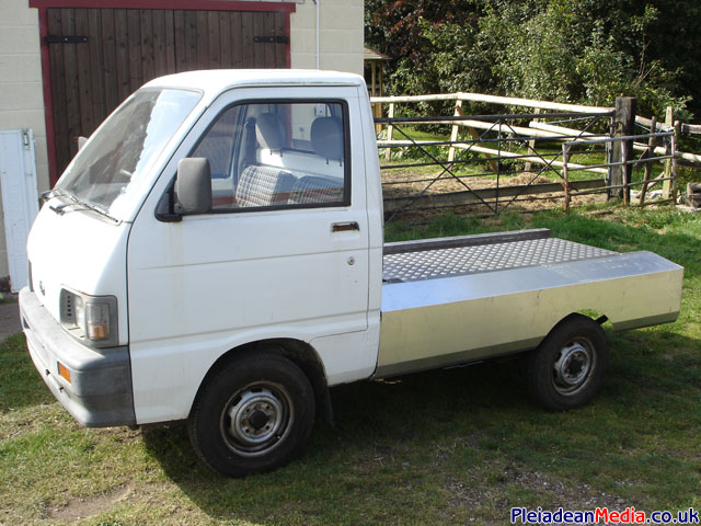
Another view of the bodywork.
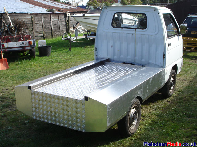
Yet another view of the bodywork.
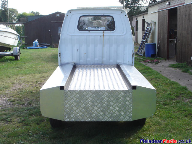
I tried the engine on the HiJet today, just to see how it looked. The length wasn’t a problem, which I thought it might have been, the only thing that bugs me a little is that it sits a bit low. This should be fairly easy to rectify.
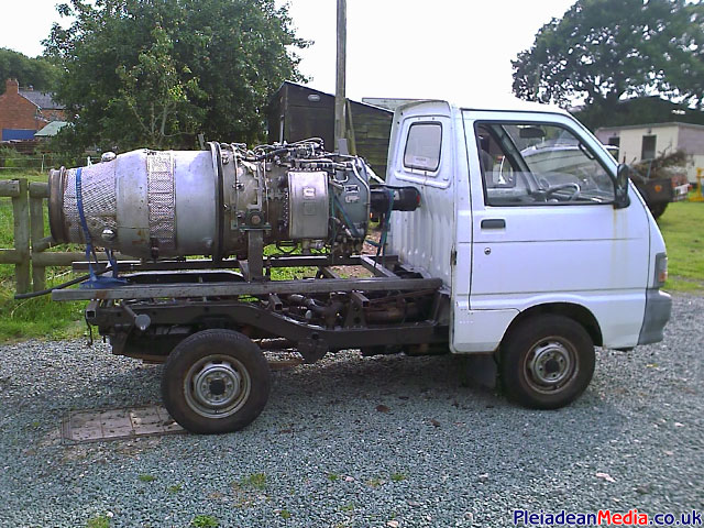
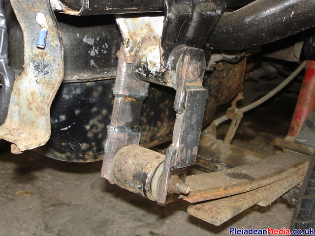
Suspension sorted, I cut the links in half and extended them by 40mm, this should compensate for when the Viper is mounted to the vehicle.
Today I started fitting the LED lights which give a crisper and brighter colour as opposed to normal filament type lamps.
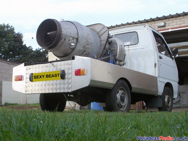
I need to enlarge the wheel arch’s and change the profile of them a little. Things are coming together, Slowly and Surely, as Richard Burton once said.
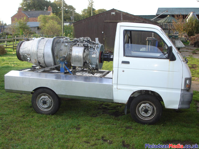
Full set of LED lamps now attached and the engine frame has had a coat of paint. I have to say the worst paint job I have ever done, I guess it will be a sand down and repaint job when I get chance.
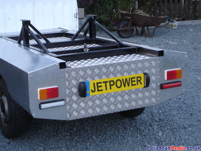
Its been bugging me for ages, so while I have had a spare bit of time I removed the Vipers bulkhead, which is a standard fitment on the engine. I think it looks a lot better and more jet engine like.
Time to pimp it up a little, It seems that the HiJet is unique in the fact that the wheel studs are of an odd diameter (PCD) of 110mm, this PCD seems only to exist on quad bikes and trailers. I spent a lot of time measuring and trying various PCD108 wheels to get an idea of how big I could go, eventually I decided that 15″x6J rims would do nicely while also providing suffcient clearance.
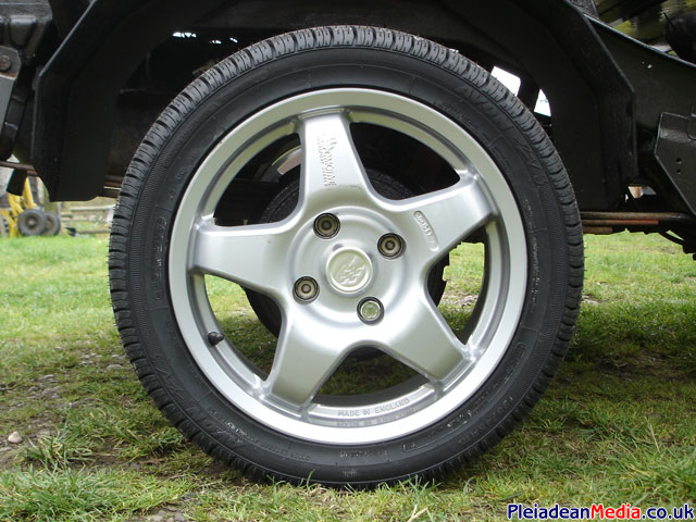
Combined with a set of Avon 195 45 R15 tyres, I feel that they add a large improvement on appearance from the original 12inch rims and 155 80 R12 tyres.
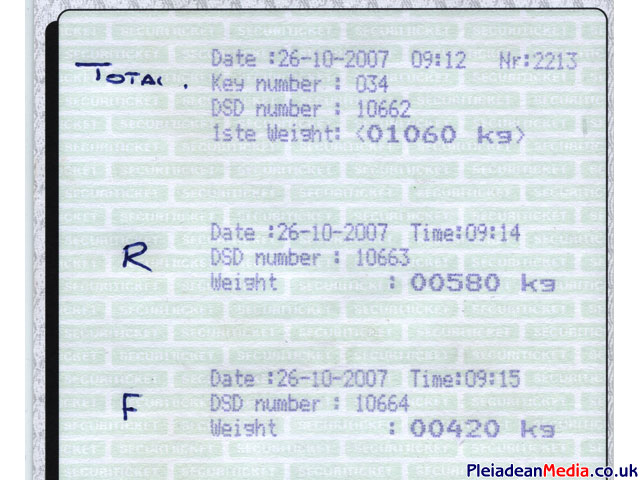
Time to see the current weight status using the HiJet drivers manual as a reference.
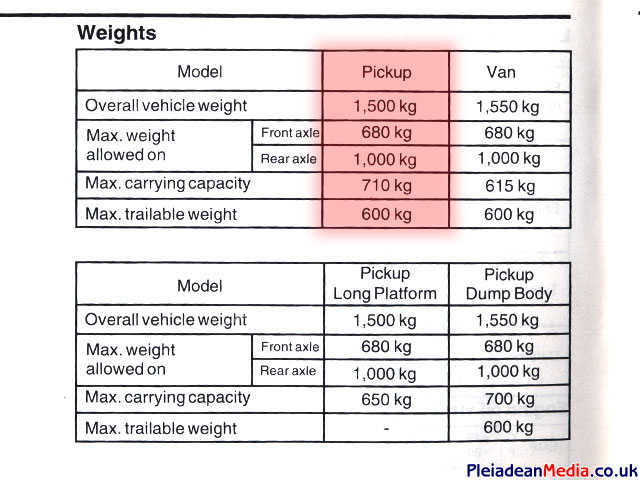
Good news – all within limits.
440kg Spare on the total weight.
420kg Spare on the rear axle.
260kg Spare on the front axle.
This means that adding the battery’s and fuel tank is not going to put me over the legal weight limit.
This is the template for the fuel tank which is made from 1″ thick insulation sheet. I want to keep the top side of the HiJet free from bits and pieces if possible so its going to be mounted underneath starboard side. Doing this does mean that the tank size is restricted to about 6 gallons, not ideal, but enough for at least one good run at a time.
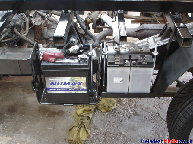
In cab control battery packs fitted on the left side of the chassis next to the Hi Jet’s battery. These are 2 x 12volt motorcycle battery’s which will be connected is series to produce the necessary 24volts. Charging will be though a connector placed somewhere in the cab.
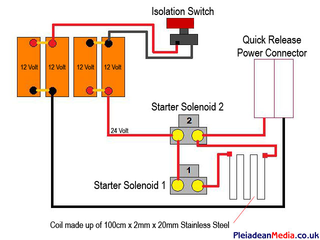
The Viper starter battery’s have been mounted in to position today. I have decided to use 4 x Odyessy PC680’s, each being 12 volt, they are configured in 2 pairs wired in parallel and then the 2 packs in series to give me 24volts. An isolation switch has also been inserted in between the two battery’s as a fool proof way of disabling the starter sequence.
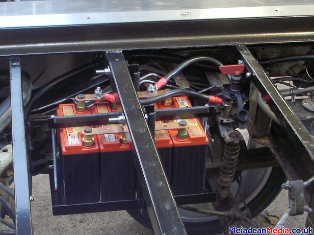
Guess where you access the isolation switch?
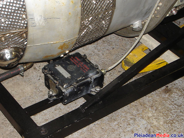
The Starter motor’s soft start arrangement fitted in place. This basically was taken directly from the trailer and welded straight to the frame. The power leads will be attached to the starter battery via a fork lift truck QR connector and the control cables to a Panzer 24 way QR connector.
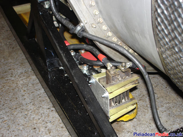
As part of making the whole Viper and frame assembly quick releasable, the Igniter box’s have been mounted to the Viper’s frame. I have a small concern about the heat generated from the combustion chamber in this area, its something that I will measure next time the engine is run.
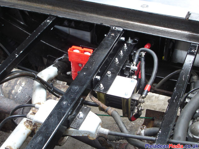
I wanted to keep all the starter cables as short as possible and implement an auto engage-disengage quick release system when the engine was mounted, this was going to require a quite a lot of cable and ultimately I decided that it was unacceptable due to voltage drop. Consequently the soft start system has now been removed from the Viper frame and mounted to the HiJet’s frame with the QR connector mounted to its side.
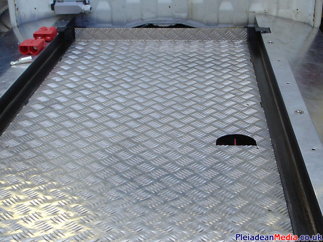
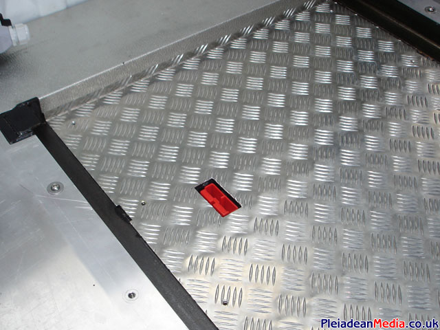
Again, not ideal in my eyes, but it does serve it’s function well, originally I was going to keep the bed hole free, but this sacrifice does mean that there is less than 2 meters of cable used. Jobs a goodun.
I recently had a few emails asking how I configured the soft start system, so here is a basic diagram of how I did it.
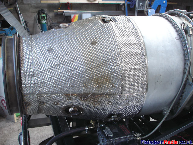
Turbine failure containment shield removed for a coat of paint. At the moment I am undecided whether I am going to leave the heat resistant blanket on, some people take it off so that the condition of the exhaust can be monitored for cracks. Its something I will decide on later.
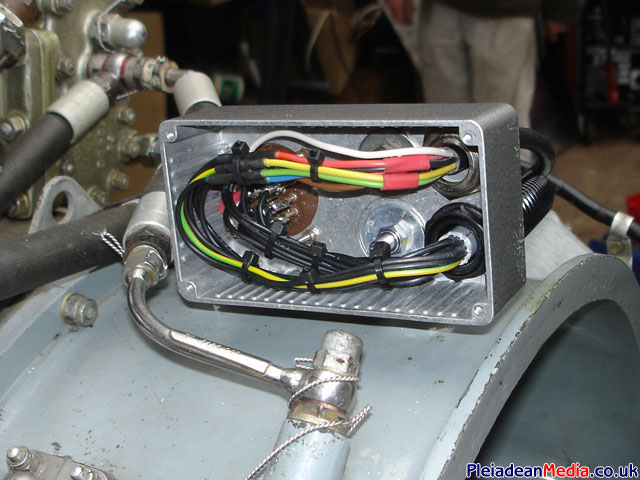
Pictured is the replacement electrical distribution box that is mounted to the Viper, the main loom enters here from the cab (bottom right) and connects to the original Viper connector (left), there is also a muticore lead (top right) out to the Igniter box’s and EGT thermocouples.
View of the connector box from the other side.
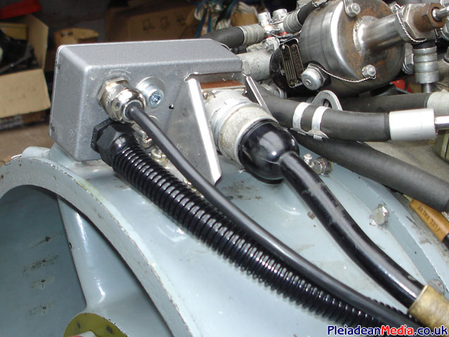
On the left hand side of the picture you can see the 24 way multipole connector that connects all of the Viper’s control circuits to the HiJet.
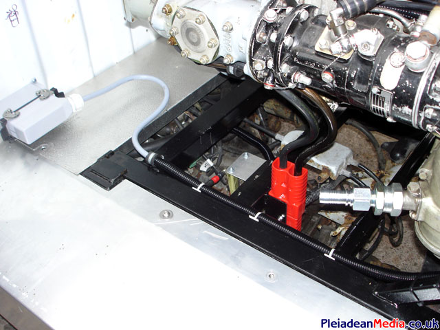
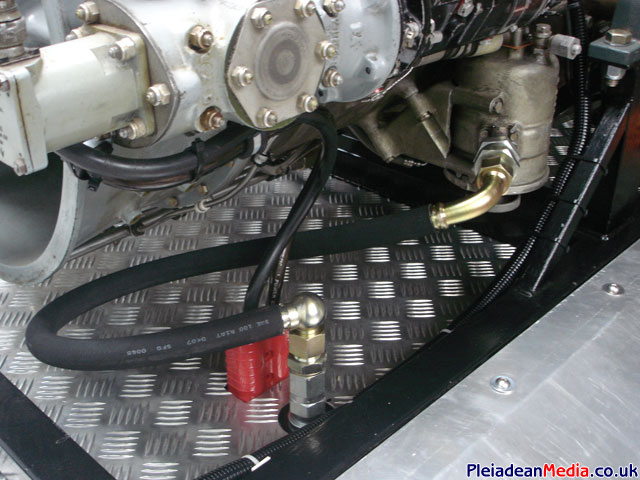
Quick release fuel system connected.
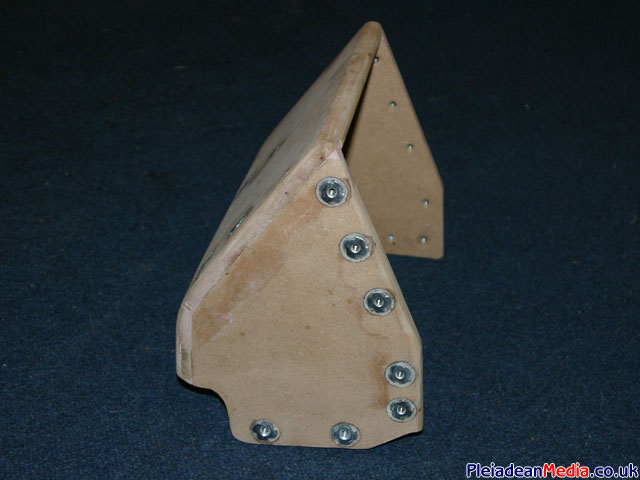
Start of the control panel that will sit on the middle of the dash, basically made from MDF and glue. The fittings you can see are spiked captive nuts, the lower ones are for attaching the unit to the dash and the front ones for the rack mounting rail.
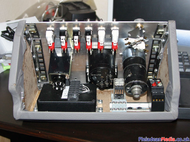
All components fitted and the MDF covered in grey stretchy vinyl. A bit of a tight squeeze, but everything I need is in there including a automatic starter cut out box that Ian kindly made me (Lower Left).
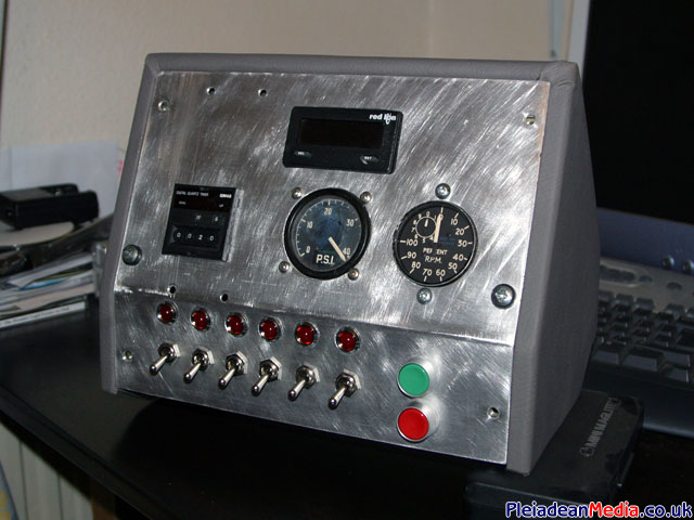
Completed control panel ready for mounting in to the HiJet. From the top and left to right:-
EGT Gauge, Fail to light cut out time relay, Oil Pressure Gauge, %RPM, Master Power, Starter, Igniter, Starting Fuel, Fuel Reset, Aux and Start and Stop Press Switch’s.
All controls have a manual override/ test facility.
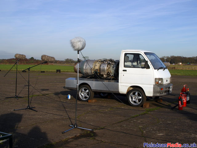
At this point in the build I received an email form a sound effect company who had an interest in recording the Viper at various stages of running for a project that unfortunately I can not currently name. I was more than happy to oblige, Ian Bennett also came along and brought his Solar T62 as a secondary engine for them to record.
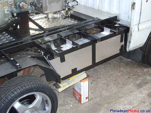
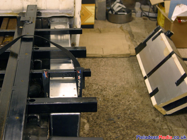
Now to fit the fuel tank, the capacity is only 5 gallons, quite a small volume really, but at the end of the day I am trying to keep weight down, it should still give me a couple of minutes at idle and a good blast down what ever runway that we happen to be on.
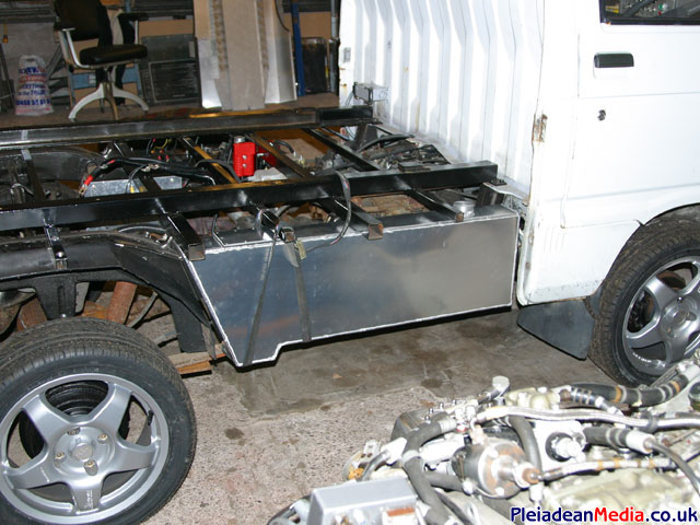
As you can see its quite slim, only 4 inch’s wide in fact, necessary to fit underneath the right hand side of the bodywork. The original insulation template can be seen to the right.
After the few starts I had whilst running the engine for the sound effects company, it became apparent that the battery’s had a limited starting capacity and were only capable of maybe 3 to 4 starts before a recharge was needed. You have to bear in mind that each start could take up to 30 seconds, so that’s a lot of electricity, but none the less I would like to have more starts per charge, so the battery’s are being replaced with a genuine 24volt NiCad aircraft battery, courtesy of Paul & Ian.
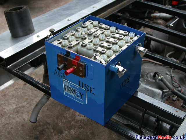
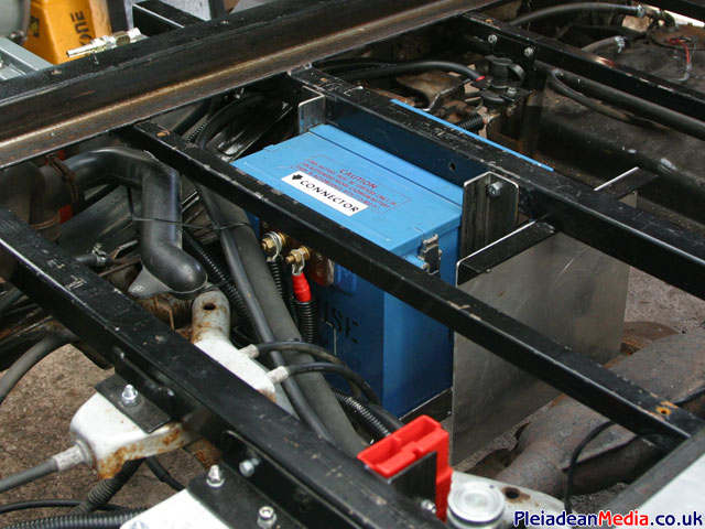
Aircraft battery fitted in to new support frame and existing wiring modified. There were a few moments of concern as to whether the battery was too deep and might interfere with the HiJet’s prop shaft, but even though its close, I think it will be ok.
Now that all has settled down some what after my little mishap with the FOD, it is time to get the throttle and HP Cock linkages sorted out. I did go to quite an expense to buy a throttle quadrant off a Black Hawk Helicopter from a chap in the USA, I thought it would be cool, but unfortunately it doesn’t quite fit and would be a real pain to mount, so I have opted for a real basic, but simple lever assembly, knobs yet to be mounted.
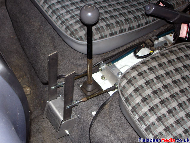
I have opted to use push/ pull cables for the control linkage , fortunately there is a company only 35 miles away in Ellesmere Port that manufacture them. I paid them a visit and within a couple of days they had made me two cables to my specification.
Their web site address is http://www.rdb93.co.uk/
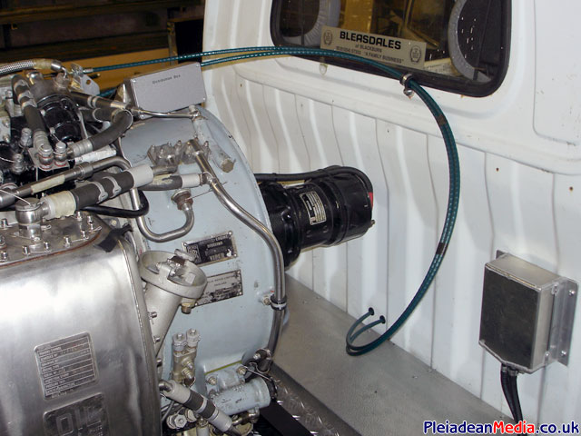
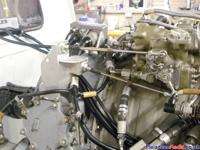
Control linkage mounted to the engine by a specially made aluminium bracket as there is no aircraft to bolt the cables to. Ball joints are used this end, clevis joints are at the cab end.
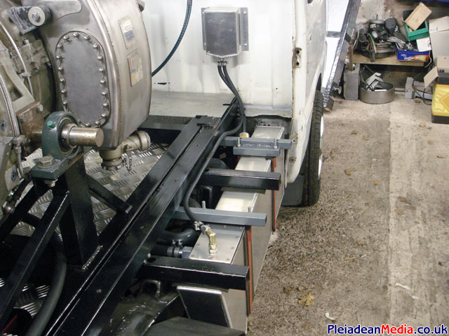
I have fitted a breather/ catch tank made for me by alumacraft to the fuel tank and bolted it to the HiJets bulkhead, this will guarantee that no fuel can escape and as it has a filter on the input side can provide clean filtered breather air.
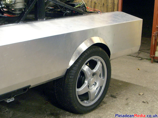
To make the pickup legal in the UK, the wheels are not aloud to protrude from the side of the vehicle. This means another trip to Alumacraft so that he can weld some ‘wheel arch spat extensions’ to the rear side panels – as shown.
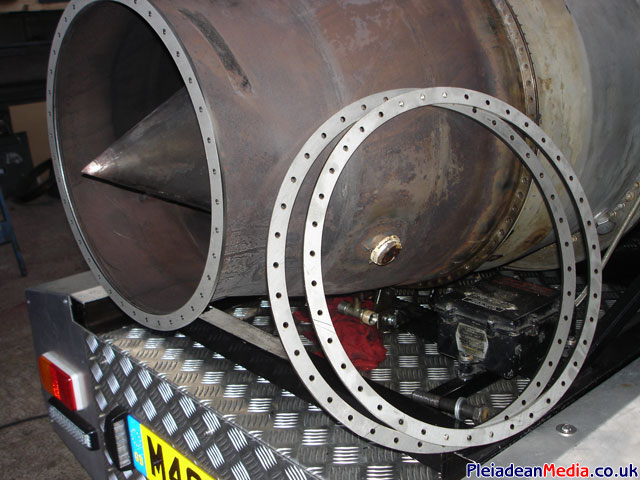
Time to increase the Vipers power by adding a jet pipe. Originally I thought this would be as simple as buying an old jet pipe, cutting 2 meters out of the middle and welding the two ends together – simply not so. It seems that the 100 series viper jet pipe is actually held in place by the aircraft and consequently there is no retaining clamp on the engine, this means a flange has to be welded on to the end of the exhaust so that a matching flange welded to the jet pipe can be easily fitted.
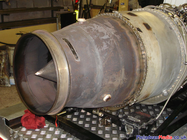
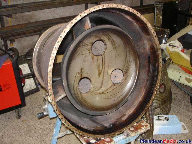
Exhaust removed and a view through it that you normally don’t see.
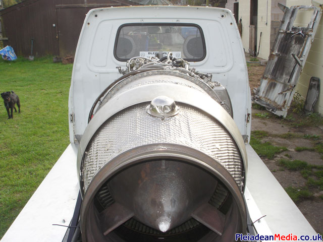
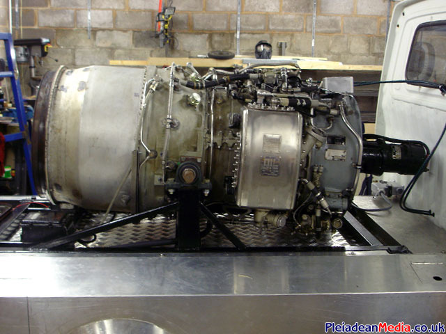
A stubby Viper left on the back of the pickup.
The turbine wheel disc is literally at the back when the exhaust is removed.
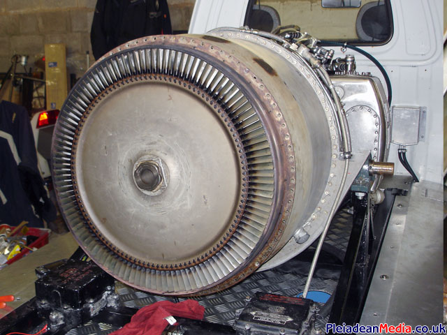
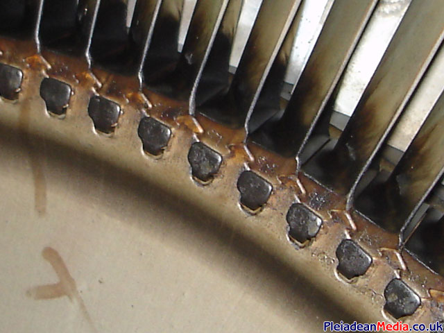
A close up of the turbine blades showing the ‘christmas tree’ type retaining fixing and the locking tabs that keep them in place.
This bit hurt. When cutting in to a beloved item, you always wonder if you are doing the correct thing. There is no need for the existing sealing ring as it no longer has any use as it is being replaced by a flange , so I have cut it off! As a benefit, it will help reduce the overall length of the engine.
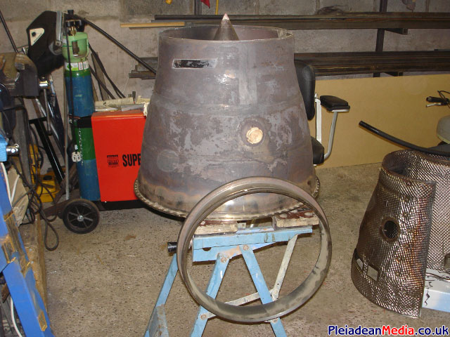
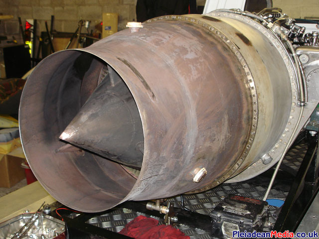
I think it looks quite good like this, but all will change when the flanges get laser cut and welded on.
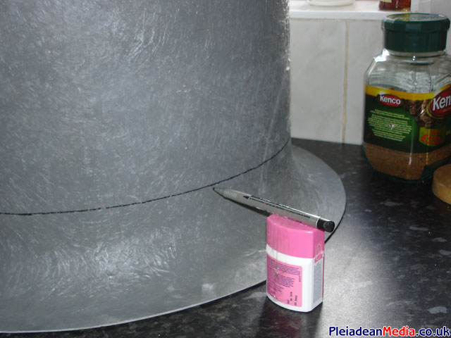
To improve the efficiency of the engine it is important to smooth the air flow in to the compressor. To help do this I have purchased a hovercraft guide duct from K&M Products. Its not quite the size I require, but it’s the nearest I could find and should fit with some modification.
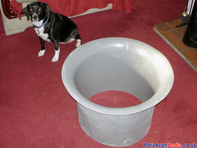
I pride myself on first class design and fabrication. As you can clearly see I am using a vitamin container with a pen sellotaped to it to mark out the final depth of the guide duct.
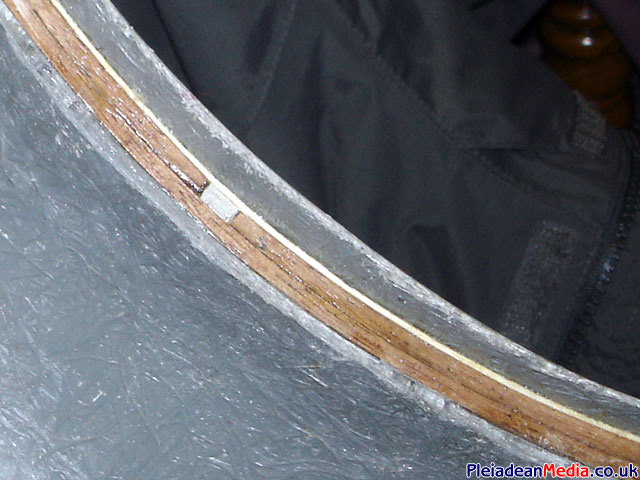
With the trumpet now cut down to size the next job was to make the internal diameter size the same as the compressor inlet housing. The trumpet duct is 20mm larger in diameter and by steaming three pieces of thin wood, and then fibre glassing them in place the space difference was made up.
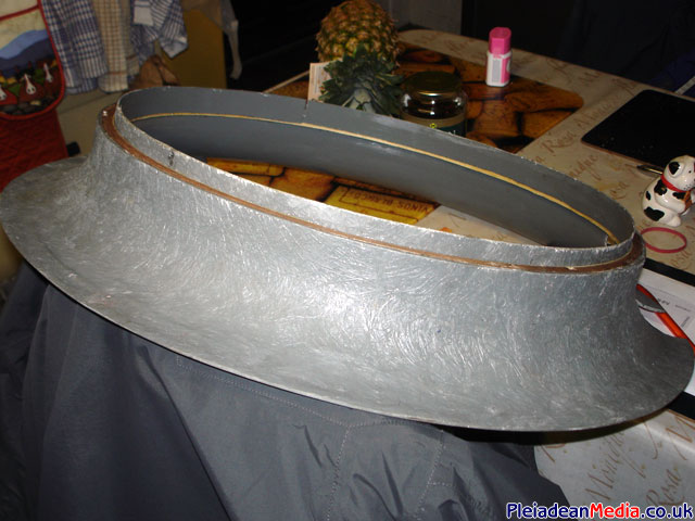
From the off-cut of the hovercraft duct I cut a 40mm round strip, this was then epoxy’d to the inside of the duct and overhung by 10mm, this will, when finished locate snuggly inside the compressor casing, holding it firmly in place.
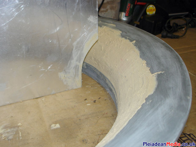
I have now filled the internal gap with filler created by adding the wooden spacers so the next job is to profile the trumpet intake to a constant curve using a cut off of aluminium as a template.
I then covered the whole inside of the trumpet with a layer of k-glass, carbon cloth and then laminated it with some epoxy resin, all I have to do now is secure it in place.
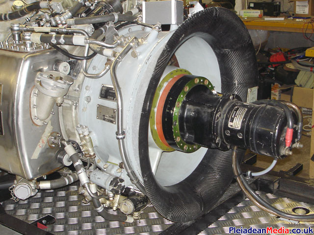
Now to the exhaust/ jet pipe. The flanges for a nice professional appearance and high tolerance have been laser cut by ‘Laser Process’ of Cannock, I have had three made, one for the Vipers exhaust, one for the jet pipe and a spare just in case I add a reheat sometime in the future. Reasonably priced to!! Next I’m off to see Derek who’s going to to the welding.
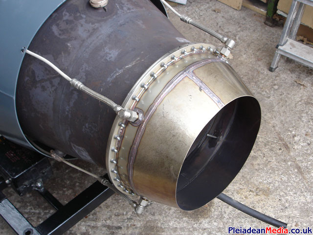
Jet propelling nozzle fabricated and fitted. The four thermocouples are held in place by 3/8 BSP Stainless Steel fittings adapted and welded in to the Jet pipe.
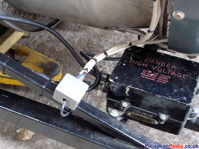
The four wires from the thermocouples are wired together in parallel and secured in a tamper proof box which is attached to the Vipers frame. I popped down to my local runway to try out the new Jet nozzle. 100mph very quickly indeed and also a new pair of pants required, all good stuff.
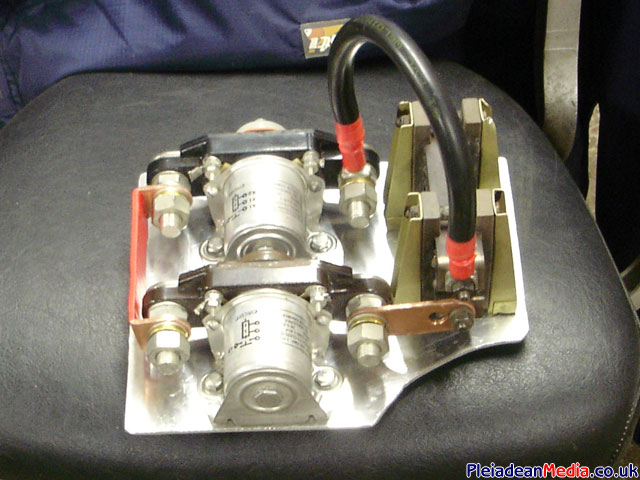
Just after the 100mph run and once I arrived back home, I was just doing some basic electrical testing on the circuitry and the soft start solenoid failed, blowing a couple of fuses. So now was the time to upgrade to some 400amp aircraft solenoids, at last a proper job and I feel happier about the system.
Thanks to Rob, the rear end of the HiJet has now had a coat of paint. Its a shame it makes the front end look so crappy.
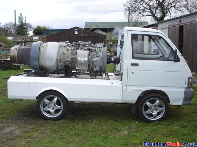
The front will be painted sometime soon, (when I get chance) and some aircraft decals will be made from vinyl, saying that I have yet to decide on the type and colour scheme of the stickers.
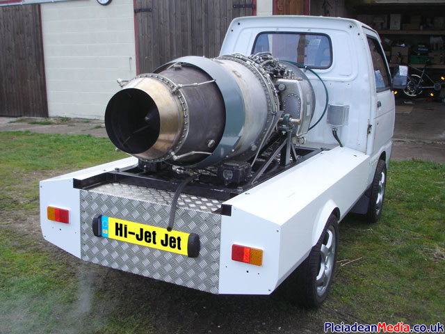
DOOM !
Today I had a test run up to check out the new aircraft starting battery. At around 60-70% RPM, there was a loud whoop type noise, the engine flamed out and was it at standstill within 10 seconds! The HP Cock was swiftly placed to the off position and I was left with wobbly knees and slightly tearful, also clueless as to what had just happened. After I gathered myself together and had a quick inspection, it became obvious that the engine had been FODDED with a fairly large piece of yellow cloth. Don’t know where it came from, but there you go, it was there. The engine was extremely stiff to turn, impossible by hand and at this point I was convinced that the engine was a right off. I quickly took the viper back to the workshop, where an intelligent guess was that the last 4 stages and had effectively centrifuged the material outwards on to the outer compressor blade tips where they acted as friction between the outer tips and the compressor case. I administered a large quantity of WD40 in the hope that this would free it up and also by turning it over on the starter would expel the cloth, a bit of wishfull thinking unfortunately and the starter may have been damaged during this procedure, time will tell, It has been decided that the only option will be to remove the compressor case and remove the foreign material by hand.
The stator blades have virtually no large debris on them, this is a relief, but is also kind of expected, more importantly there is no obvious damage.
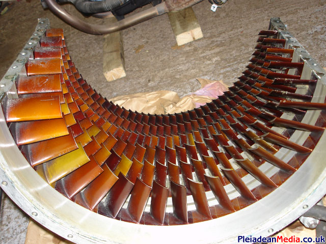
You may notice that there is a film of cloth residue, on the stators, this comes off easily.
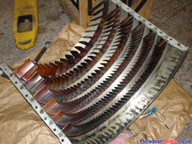
The scary bit, obvious cloth ingestion as expected on the outer blade tips.
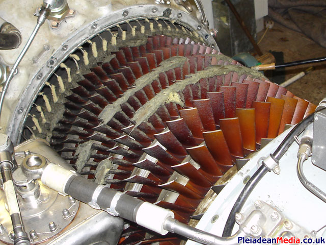
Using tweezers and a vacuum cleaner we carefully removed all vi sable cloth fragments, as you can see the combustion chamber guide vanes have caught a fair quantity of material.
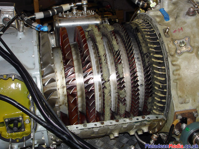
So far there seems to be no damage to the rotor assembly, the top case will be replaced and the lower compressor segment will be removed and checked.
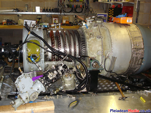
The engine has now been put back together and has had numerous runs including a 60 second 100% run.
We decided to give the sound chaps a real flyby, but with no throttle fitted, I improvised, mainly by getting Ian to sit on the Viper and control the throttle and HP Cock whilst on the move.
He later complained of a hot bum! No pleasing some people!
Time compressed video showing the removal of the Vipers upper compressor casing. The actual time was estimated to be 3 1/2 hours. Taken from one of the security cameras in the workshop.
The engine idle setting was wrong and now has been amended, you can tell this because the flame disappears just before shutdown (just after idle was reached). It may look like a hot start, but being filmed at night exaggerates the flame and consequently the camera hunts for focus.
A television feature shown on ITV’s Pulling Power.
Thanks to all that helped filming. Paul for the use off his Monaro chase car, Graeme, Ian, Phil and Roland.
No Audio Unfortunately.
No Audio Unfortunately.
Apologies to Paul for dinking his new Helmet.
