I had the opportunity to buy a potentially blown unit, it was cheap thanks to the seller and thus worth a gamble. After a bit of effort it’s now working again.
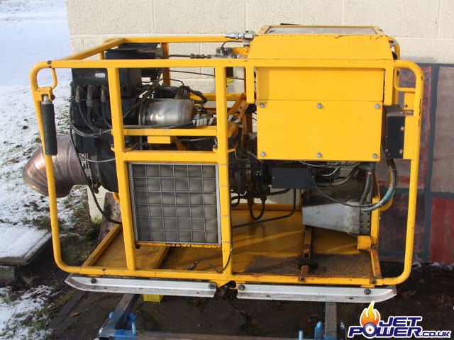
The Lucas GPU as it was delivered, in ok condition and a with very suspect oil leak from underneath.
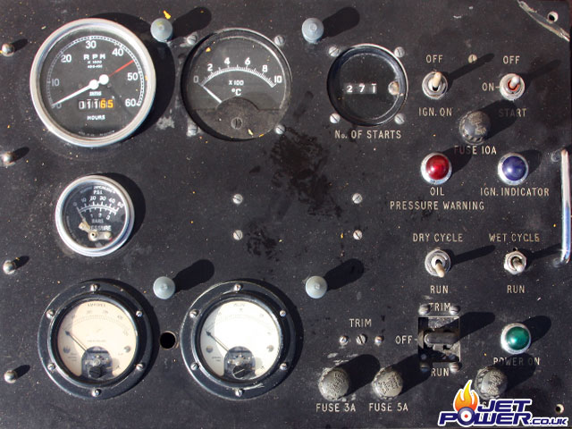
The control panel of the unit, showing 1165 hours of use with 271 starts, this equates to about 4.30 minutes per run.
The dynamo assembly, this is also suspect and is possibly on its way to being seized.
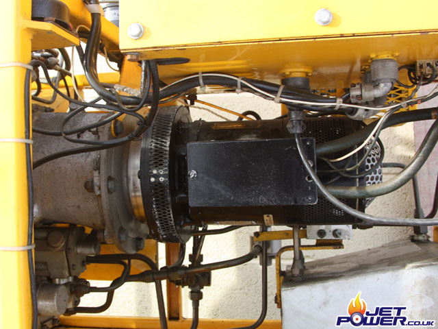
A clear view of the generator retention bolts.
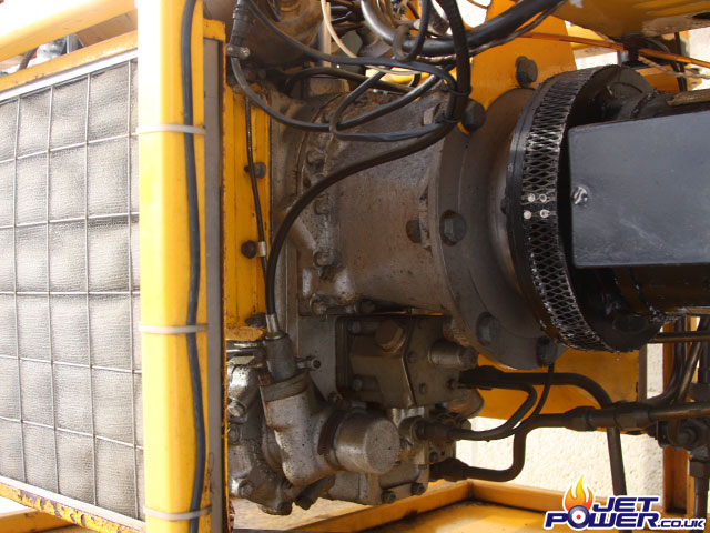
Generator removed showing the drive coupling.
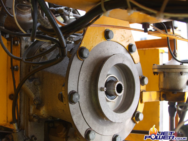
Not in the best condition and is incredibly hard to turn, but I’ve not given up on it yet.
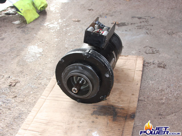
I have decided to make a replacement, smaller frame for the engine, this means stripping the unit down to its individual components.
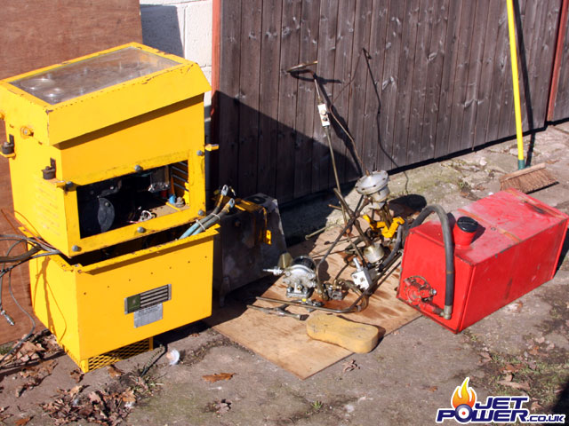
One frame minus all the important bits and pieces, this will now be cut up and scrapped.
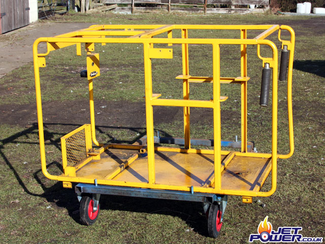
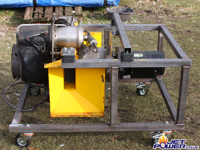
One basic frame fabricated which will hopefully allow the 1S60 to be easily viewed in all directions and four 100mm castor wheels attached for easy transportation. I have used car engine mounts to fully shock mount the engine.
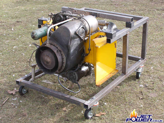
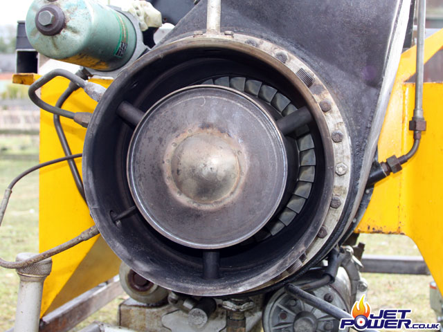
The turbine wheel.
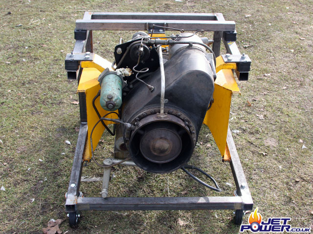
I may cut down the air intake/ air filter housings, but that will be a job for later, this would expose even more of the engine.
Air/Fuel Emulsion Pump at the top centre, with the offside combustion chamber just below it.
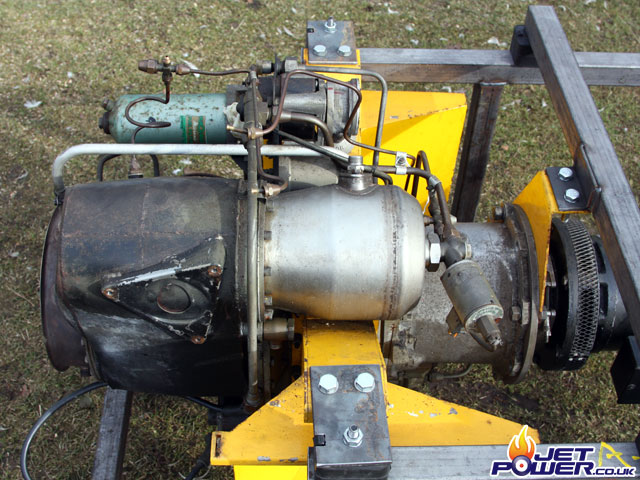
Air/Fuel Emulsion Pump centre and the fuel filter assembly to the lower right.
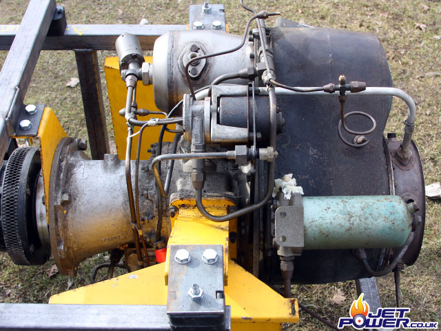
Another view of the engine, the oil pump can just about be seen at the bottom, with pipes emerging from it.
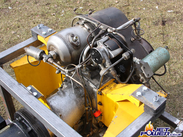
Side view of the engine and air intakes.
At this stage the generator was removed and placed in a large vice, the field coil was energised and 24 volts applied to the main connections, thus turning it in to an electric motor. The generator was run like this for about 30 minutes and it loosened up the tightness to a point that it could be rotated with two fingers.
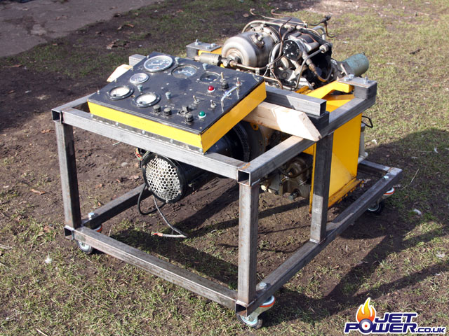
Rather than making a new control panel from scratch, I have decided to make use of the original one. The original metal containing box has been cut down and attached to the frame using a piano hinge, this practice will save time and money.
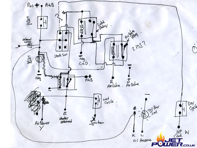
Using state of the art pieces of paper and a pen, I came up with a revised circuit for the main interface box connected to the engine, as always I try to make use of original parts as much as possible to save time and and money.
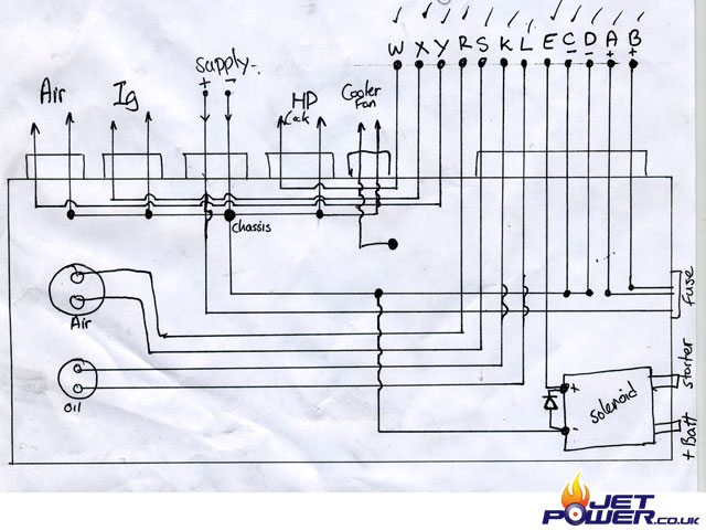
I’m proud of this one, shown is the wiring diagram of the control panel.
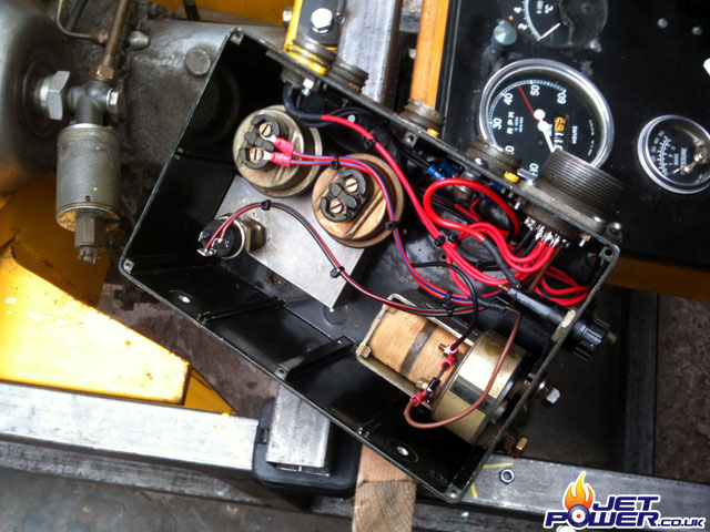
Shown is the interface box that was mentioned above, the components: air pressure switch x2 (only one used), oil pressure switch, starter solenoid, fuse holder and multi pole connector.
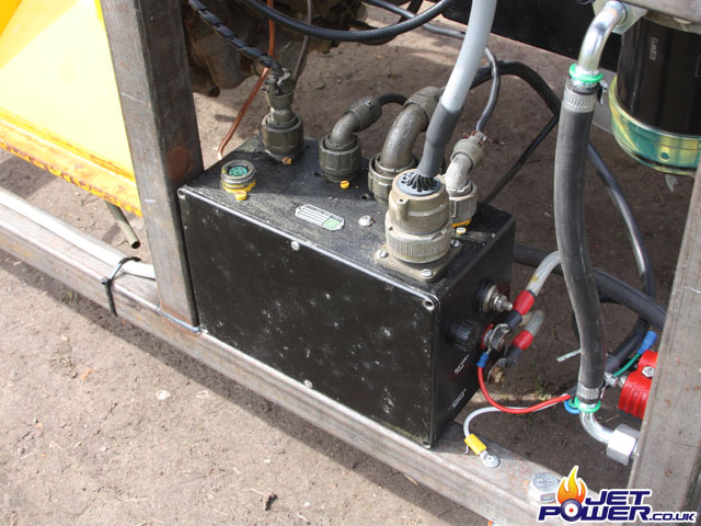
Interface box mounted to the engine frame.
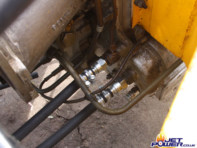
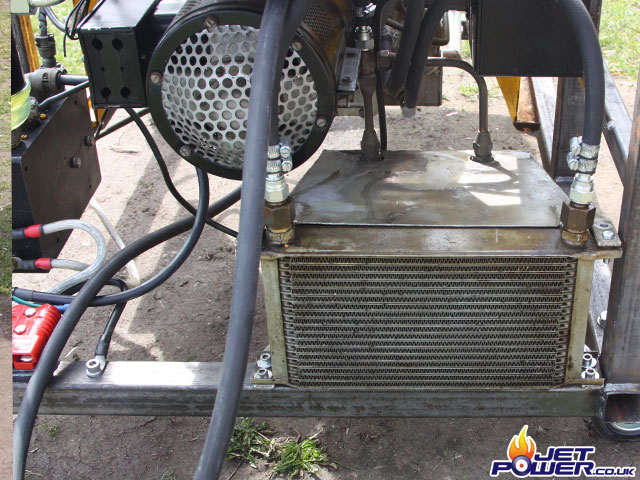
Oil pump feeds to and from the oil cooler.
The oil cooler has an induced venturi effect air flow over it’s vanes by tapping some compressed air from the compressor section of the engine, no electronic fans here!
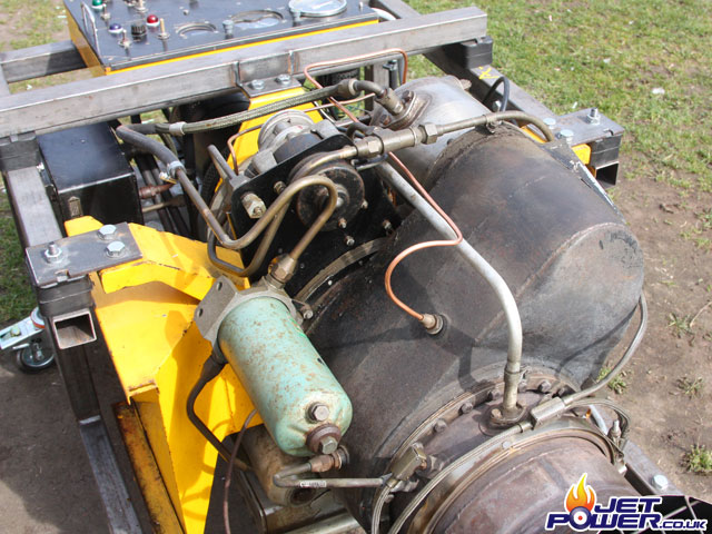
The small copper pipe shown just off centre connects to the air pressure switch in the interface box, when the pressure gets to a pre determined level, this switch then deactivates the starter solenoid, igniter and air emulsion pump.
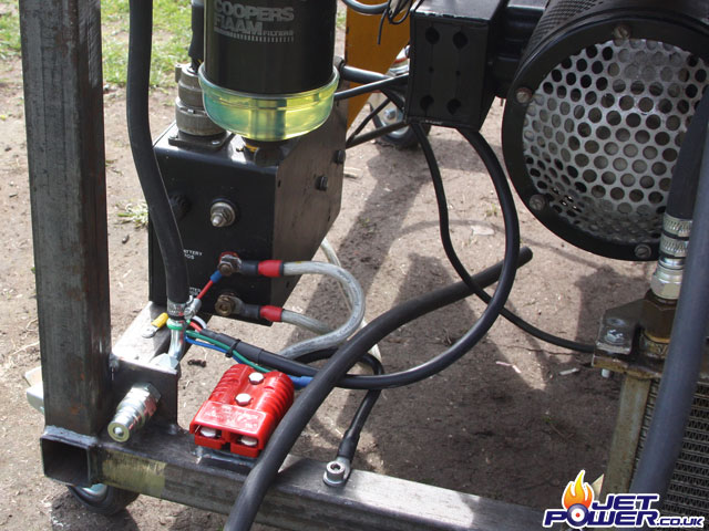
Standard 24 volt anderson plug supply’s power to the engine for starting.
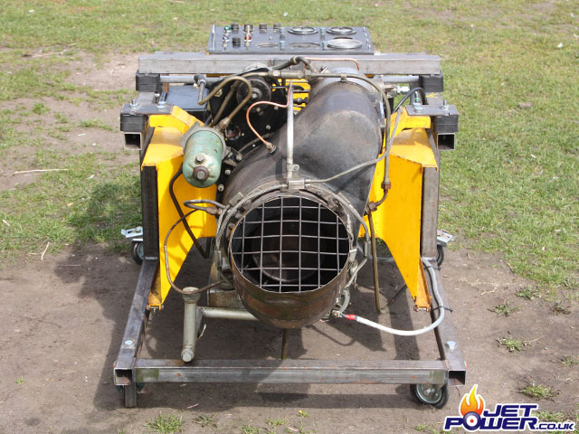
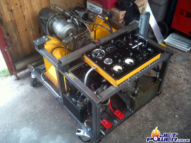
Nearly finished rover 1S60 GPU
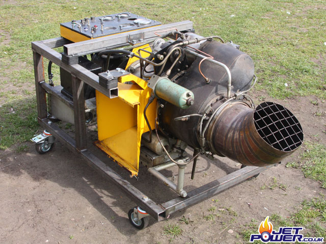
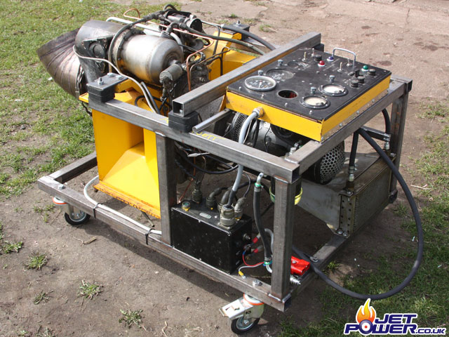
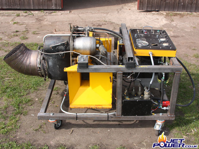
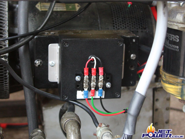
Now to get the generator running, Ian has kindly made me a 24volt regulating control box that I have attached to the genny itself, basically it controls the voltage to the field coil, thus maintaining the required voltage.
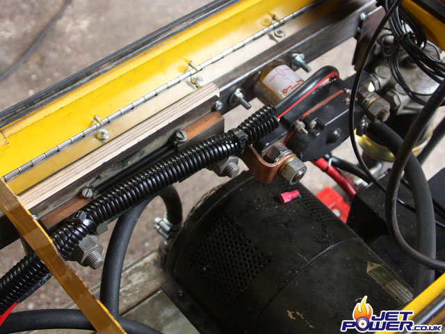
The positive from the generator connects to a 500 amp solenoid so that the power can be isolated during running, and then from that to an ammeter shunt so that the current can be monitored, the voltage and ammeter gauges on the control panel now once again have a use.
Then from the shunt the power leads originating from the generator terminate in to an anderson power plug, shown right.
Video showing the dynamo being ‘broken in’ by using it as an electric motor.
Using Ian’s BMW to start my Rover 1S60.
Running my Rover 1S60.
