A low power APU rotating assembly test, the Olympus is being powered by a Williams WR-27 air producing turbine engine and is probably the first time an Olympus has been turned over since 2003. This is known as a dry crank, no fuel is being fed to the fuel injectors and the engine is not running by itself.
A dry crank full power APU engine test. The air producing APU being used is a Garrett GTCP85, possibly one of the air producing turbines approved for starting the engines on Concorde.
Another dry crank test.
Testing the high energy exciter and plugs, please excuse the crackling sound, I think the video camera was giving up on me.
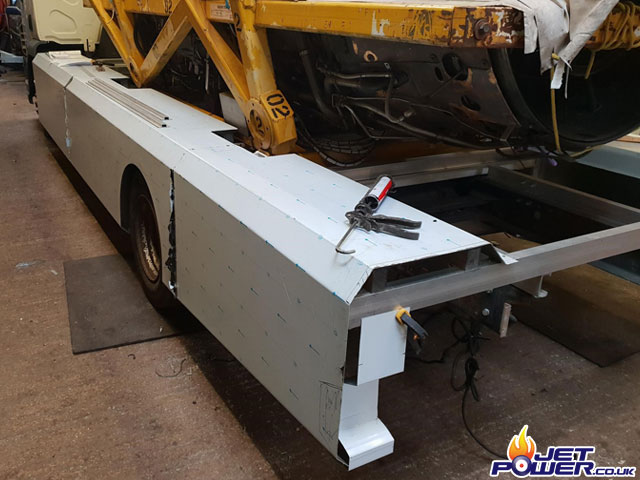
My Lorry died, it had been sat around for so long it became a lump of rust unfortunately, so some time later once I had saved up enough I bought another. I wanted the lorry to look quite smart as to complement the Olympus so I took it to my pals at Euro Horseboxes to get a make over – Side skirt frames attached.
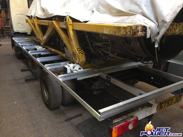
Your starting to get the idea now, the centre of the floor will remain open for access to the underside of the engine.
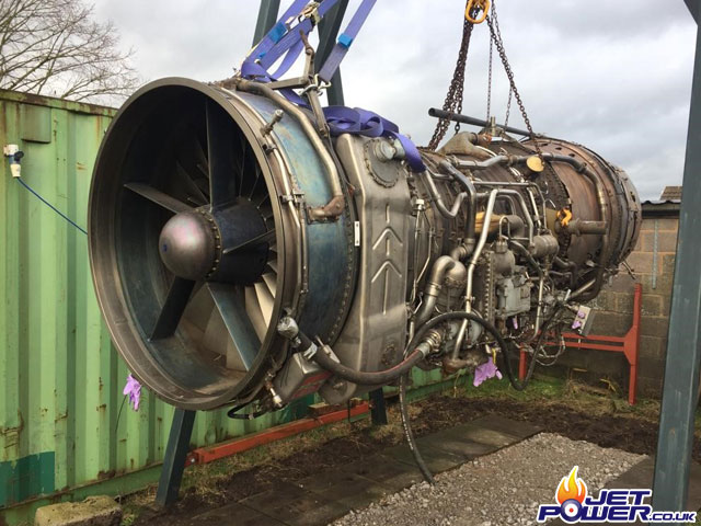
And the engines frame also needed some maintenance as it was becoming rusty, so a make over was also in order which meant removing the 593 from on top of it. Quite a nervous moment I have to say.
Rustry parts removed and frame strengthened.
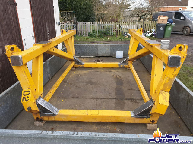
Sand blasted and primed ready to go to the painters.
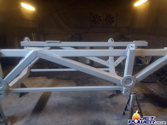
Ant and Jon popped over to give me a helping hand.
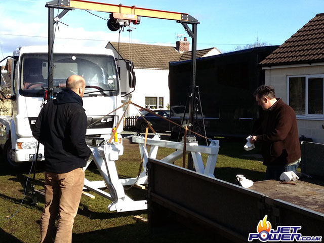
Frame attached.
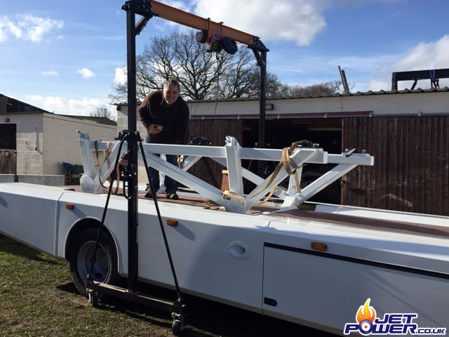
Although fitted, the centre set of boards will come out for normal use allowing access to the underside of the engine if required.
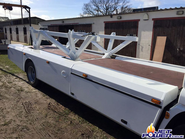
It was a bit of a tight fit getting the engine back on the lorry, letting the tires down seems to help a bit.
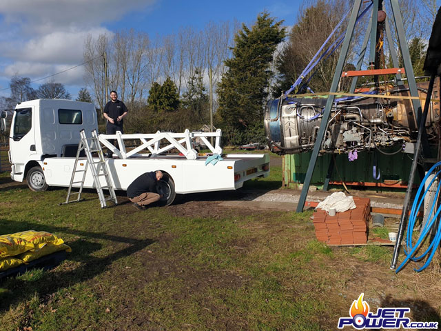
Fitted and secured.
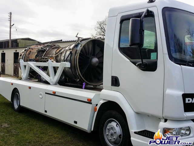
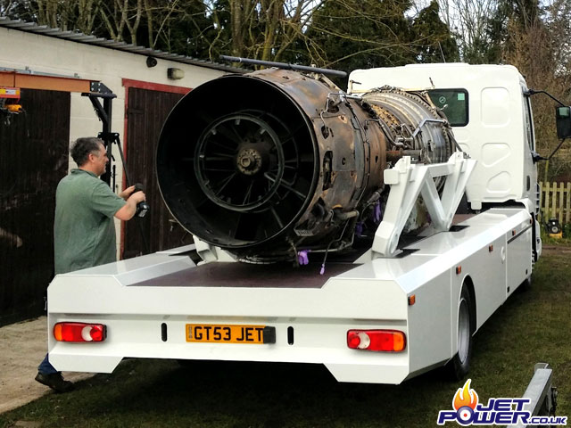
Final adjustments.
We spent just over a year trying to electronically simulate a control system that replicated Concorde’s throttle control and it was all in vain. My mate Jon who was having a crack at it admitted it was just to hard to do without a lot of spare time and resources, thus we had to chose to go down a different route and make our own throttle actuator.
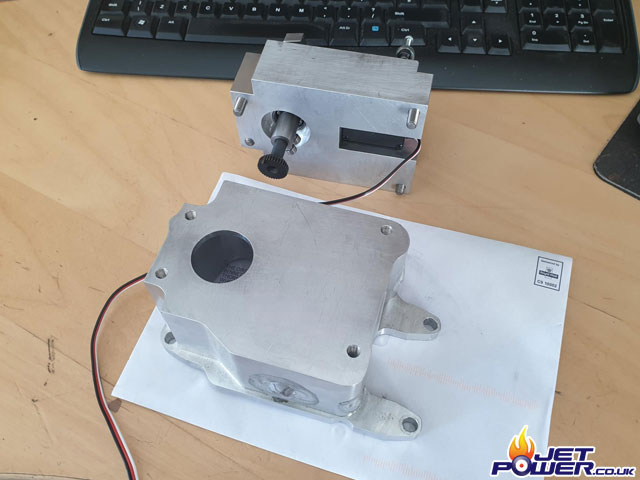
Time has moved on somewhat and again the one thing holding the project up was the throttle actuator housing and associated electronics. Pictured is the housing as it stands at the moment, its taken nearly two years to get to this stage and although a beautiful thing, 50% of the holes are in the wrong place. Nobody said it was going to be easy but it is extremely frustrating.
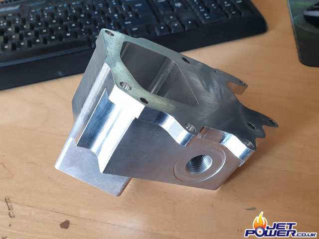
The drian holes were off centre so wouldn’t seal, they have now been blanked and re-drilled as per the 3mm sealing plate, also the housings retaining holes had lining up issues so these have been re-drilled using a mill.
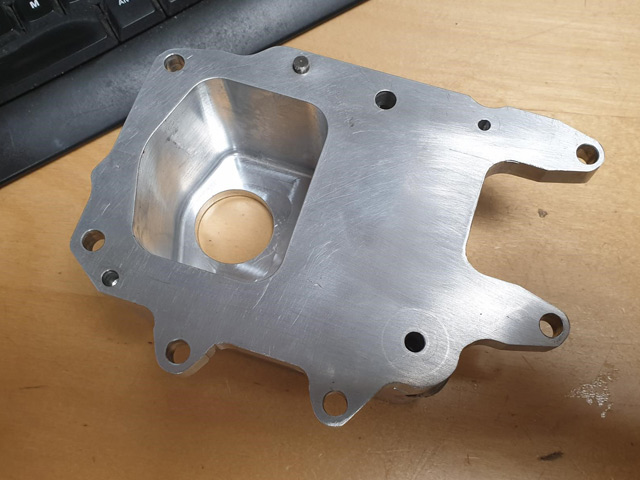
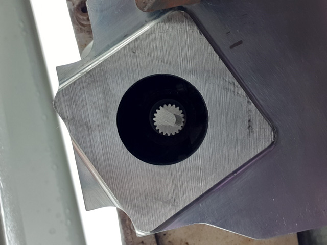
This is a pic of the housing in situ now that it can be bolted in to place. An issue with lining up to the throttle control drive spline has become apparent, this spline should have been in the middle of the recess. An additional bolt on adapter will have to me made that attaches to the housing that will contain the required seals and bearings.
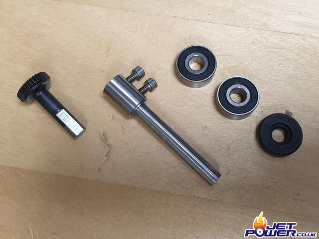
New throttle control spindle assembly, from the left:
Spindle spline that interfaces with the FCU, extension arm and bearings and seal.
Main throttle housing and bearing carrier assembly machined and ready for fitting.
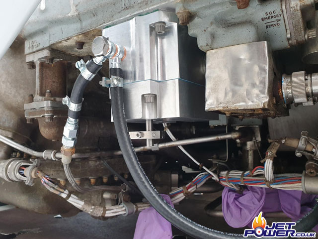
Bolted in to place, complete with fuel drains which may or may not have been needed. Without any advice from Olympus engineers it’s best to keep these things as originally intended.
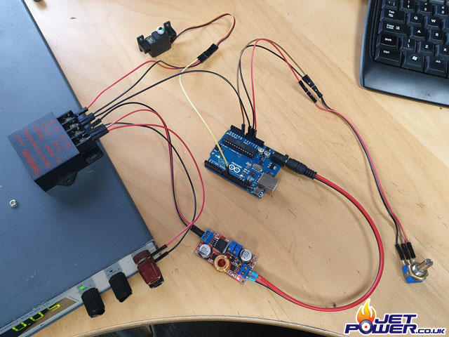
I wasn’t happy with the quality of commercially available servo testers for the use as a main controller for the throttle servo, so I have opted to use an Arduino based solution. The servo is powered separately from the Arduino to provide more power and to make sure the Arduino will not suffer from over current issues when in operation. This arrangement is just for testing, a more suitable Stepper/ Servo unit will ultimately be utilised once the engine has been proven to work.
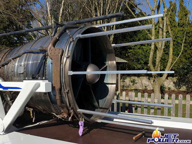
Meanwhile It’s about time I started on a FOD screen.
8 x 1″ Aluminium box as outriggers attached to the engines intake.
Media Credit: www.jetpower.co.uk
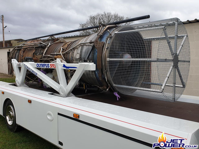
Then covered in 14 gauge wire mesh, temporarily held in place with cable ties.
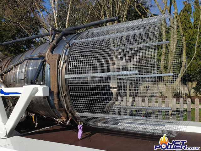
Wire locked and cable tied in to place.
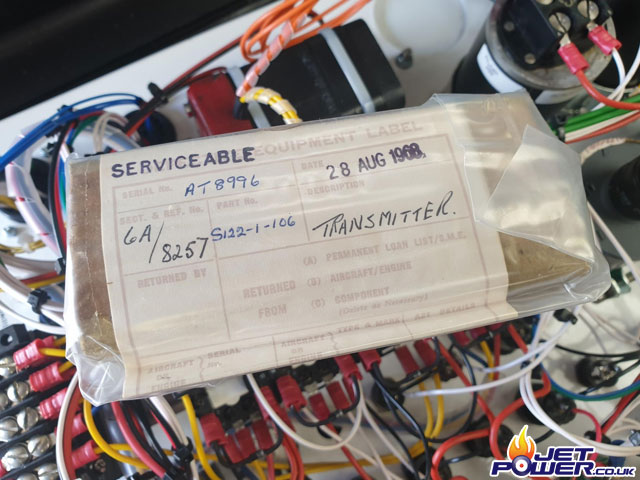
I was unable to source a Concorde Oil PSI Gauge which would have been compatible with the sender unit and after approximately 7 years of searching I am going to give up looking. I’m going to replace the original sender unit with this brand new British Weston Sender which was made in Aug 1968! This sender is compatible with Weston gauges that I have plenty of stock of and ideal at 0 to 60psi- 24 volt to, which is nice and easy to wire in.
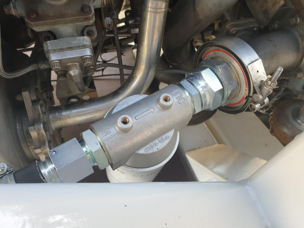
I added an additional inline filter to the fuel input, which in turn connects to a quick release coupling for easy fuel tank removal.
After a couple of bad weather weekends, we struck lucky and the sun came out. Ian & Paul came up from Bristol with their GTPC85 Air Producer and we went for a run in a local farmers field, (thank you Anthony Ford). Fuel priming took a few hours and the run was only brief due to oil pressure issues. Apart from that, the 593 was a pleasure to run, even if it did last only 8 to 10 seconds, RPM was approximately 30% at time of shut down.
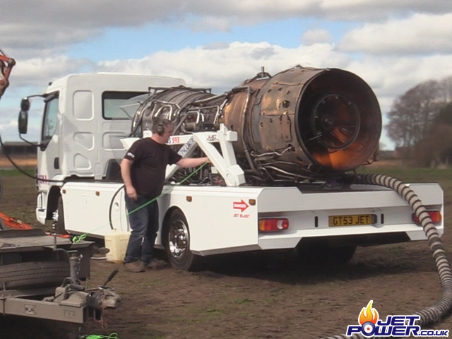
Sorry, No Audio as I forgot to plug the microphones in 🙁
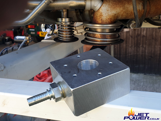
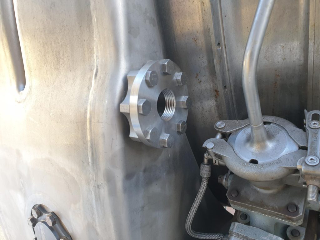
As the engine is mounted low down on the lorry the oil filler point isn’t particularly accessible, so with one of the inspection ports removed I have made a duplicate blanking plate to which a 3/4 BSP fitting can be attached and thus make topping up oil very easy.
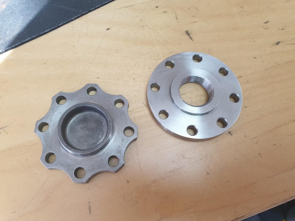
New plate in place minus it’s fitting.
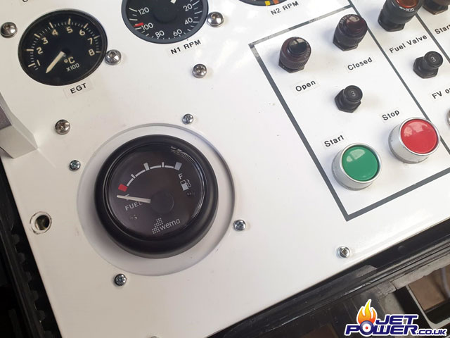
I have now mounted a fuel level gauge in to the control panel, I just need an onboard fuel tank now.
The existing front supports are great for transportation, but not ideal when running the engine, so I have made a new front support frame which is inline with how the engine would be mounted in Concorde itself. The picture below shows the frame fitted to the front support brackets. Now that all is in position and lines up nicely I will get some profile bases made which will be welded to the bottom of the legs to secure the frame in place.
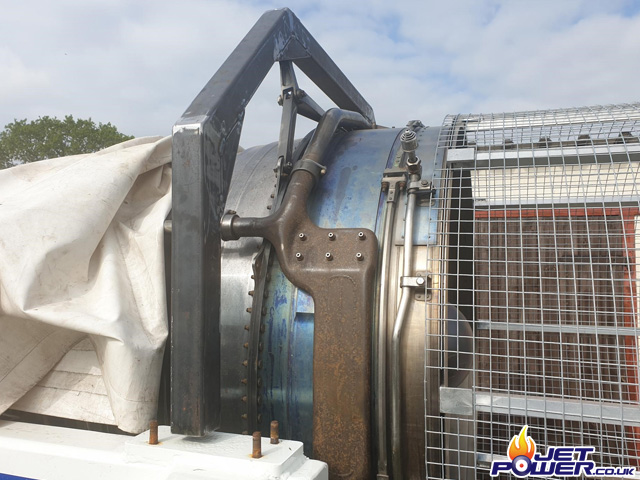
Adjustable profiles welded in to place. Now off to Cambrian Paints in Rednal for some powder coating.
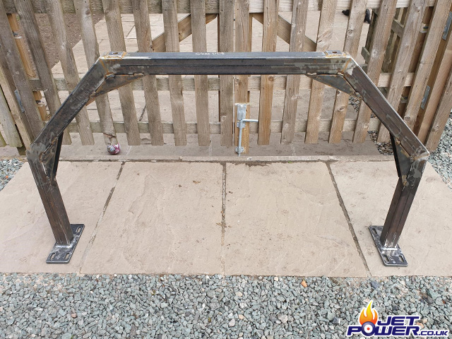
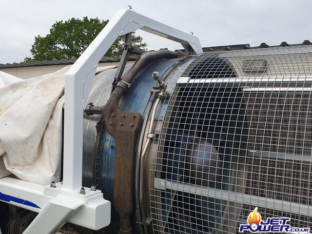
Front support frame powdered coated and fitted.
Looks pretty good to me.
After we had a few run’s of the 593, although not a major issue it was becoming a bit of a pain with the fuel vent dribbling fuel all over the place. No surprises that this was going to happen, but I was more concerned with getting the engine running at the time. Now with the current lock down in place I have removed the engine from the lorry and started making adapters so that the drain can be collected and put in to a shared catch tank.
