Welcome to my plan B. The Olympus electrical connectors when in transport are held in place with open ended blanks, these were removed from the harness and attached on to a diecast project box, this box in turn has some standard Canon ITT circular connectors mounted to it and will be used for all required electrical connections.
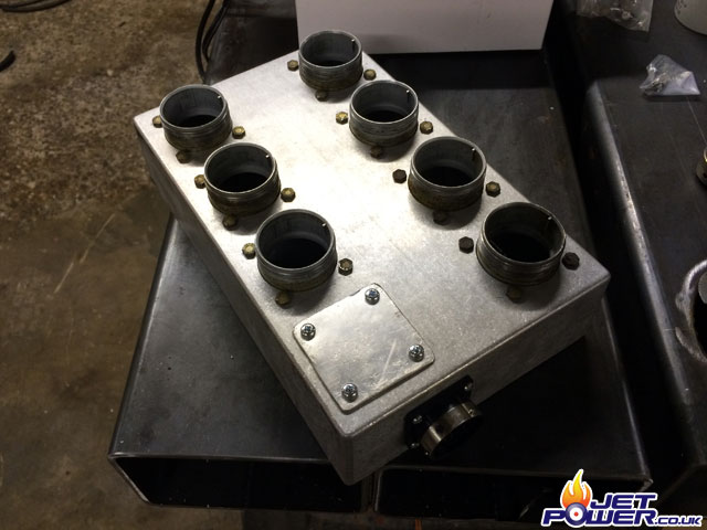
The diecast ‘terminal’ box awaiting it rear mounted plugs. I have also added feet on to the box so it can be secured to the Olympus frame.
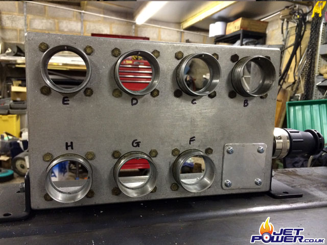
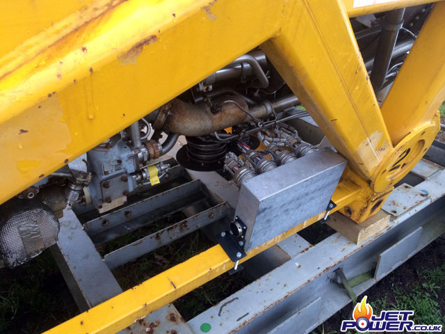
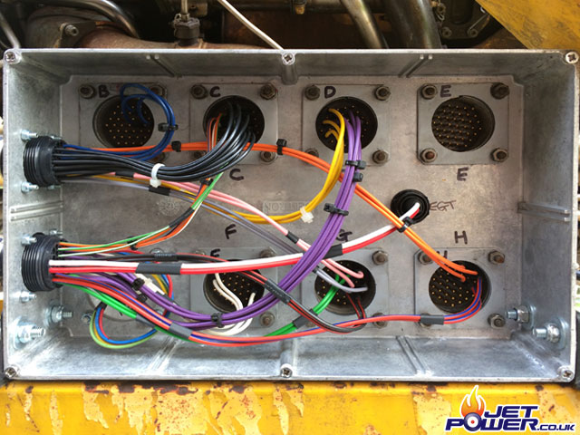
The terminal housing now secured to the Olympus frame and the engines control wiring secured to the original blanks. This leaves the plugs terminals exposed inside the box ready for patching.
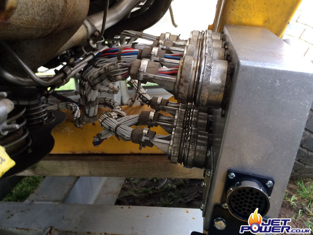
Terminal box with connections shown on the inside, this will now facilitate the box to be used as a kind of patch bay.
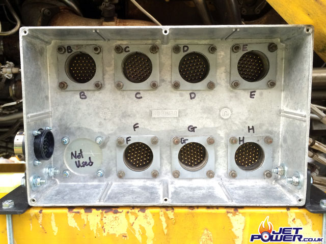
Terminal box on the engine frame, another Canon connector has yet to be fitted to the box just above the connector that is shown.
This engine is large and it would fully fill my workshop, I don’t like it being outside so I took a punt and bought a small event marquee to store it in, that night we had the worst gales in 10 years which destroyed the marquee, a bit of a low point for me.
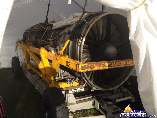
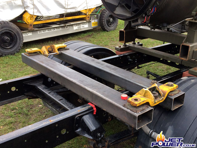
It’s time to start thinking about how I am going to mount the engine on to a lorry, all vital parts were stripped from the frame where possible and given a brush down and a bit of a clean. Pictured below are two of the four mounts that support the engine.
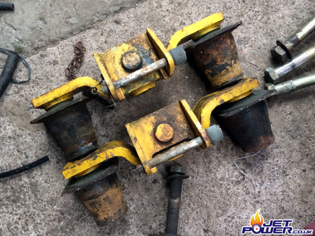
A total of four cross beams will support the engine, pictured you can see two of them with the rubber mounts in place.
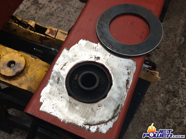
On the underside of the cross beams I have welded spacer rings so that when bolted down all is secure and play is reduced mainly due to the rubber mounts.
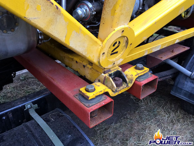
Olympus 593 mounted on to the new supports.
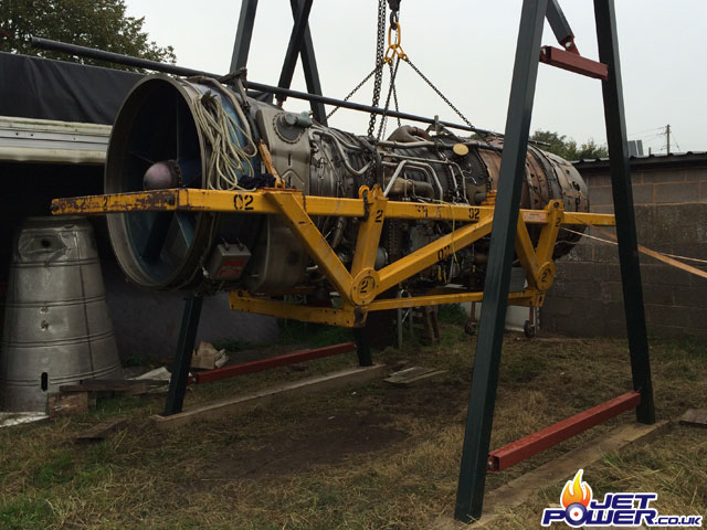
As I don’t have a Tele-handler, I had to resort to making my own lifting device, a design was drawn up by my friend Will Parry and he also had all the parts required plasma cut by his colleague Craig. A few days fabricating and I have a working Gantry, this is all considered part of the Olympus project.
I bought a 7.5ton lorry which is just capable of transporting the weight of the engine and all is fine and dandy, it passed its motor test first time which was a relief.
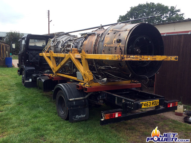
A rear view of the engine mounted on to the lorry.
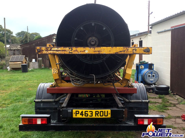
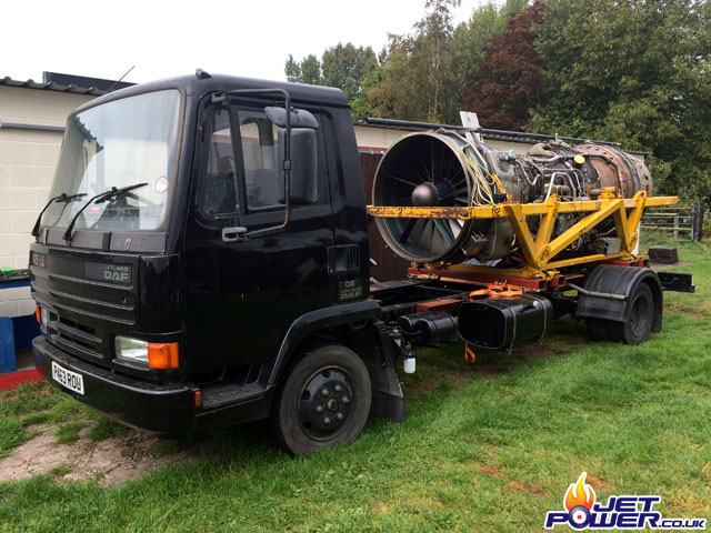
Front side view of the engine and lorry.
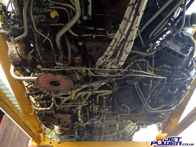
As I am now able to access the underside of the engine it was time to inspect it for damage etc, it’s somewhat daunting when you first get under there, an awful lot going on.
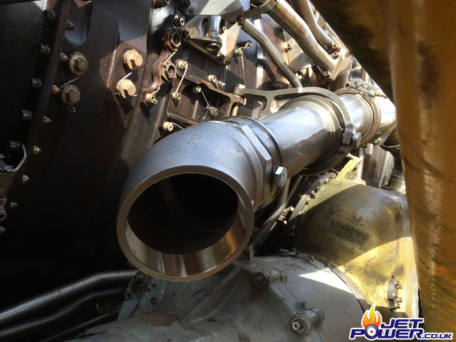
The fuel blank has now been machined down and threaded to allow a 1 1/4BSP fitting to be inserted (and blanked), this allow a secure and safe method of feeding the engine with fuel.
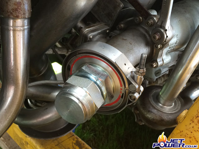
A 3″ BSP 45 degree bend has been attached on to the air delivery feed making it easier to source required fittings as it seems almost everything on the Olympus is a non standard thread or fitting.
A test actuation on the pneumatic starter revealed a fault so a remove and a strip down ensued.
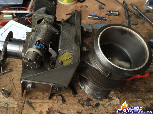
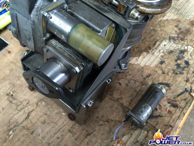
Hmm, one faulty electric motor and a bit of a weird one. The wires for it come from the front, right next to the output shaft, there is almost no chance of repairing it so I’m of to the internet to see if I can find a replacement, not holding out a lot of hope though.
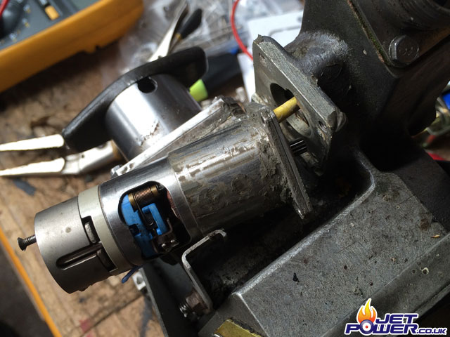
And would you believe it, I found one on eBay! I can’t believe that it was ex Concorde Olympus stock, so I presume the motor was fitted to other engines as well.
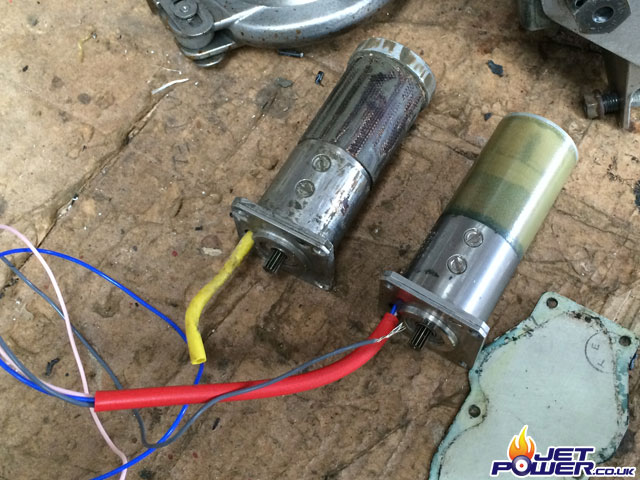
Replacement motor fitted and tested, luck was on my side for sure.
Time to remove the hydraulic pump and pipework that isn’t required. If the pump was left in situ then unless a closed loop oil system was utilised the pump would be driven by the engine dry and this wouldn’t end well, so it’s better to remove the pump altogether.
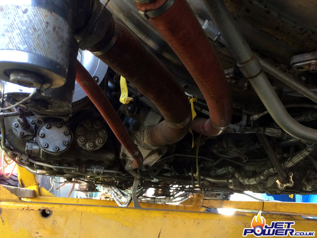
One Olympus hydraulic pump removed.
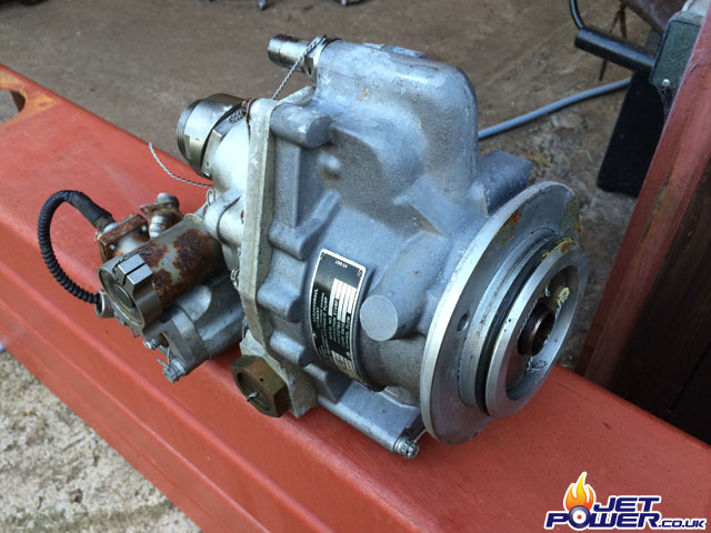
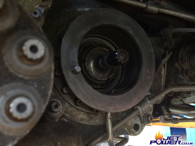
Gearbox drive and flange for the hydraulic pump now showing.
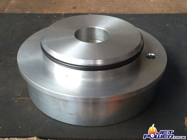
This is the blank I made to replace the hydraulic pump, maybe a bit of overkill as blanks go.
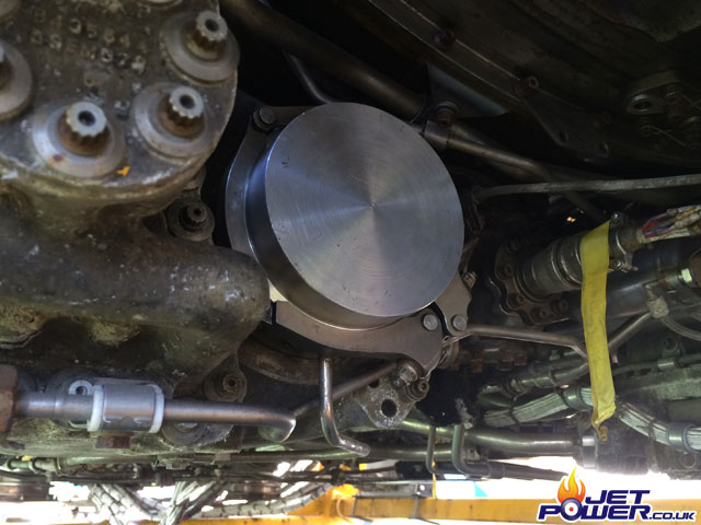
Hydraulic blank fitted and secured with a Vee Band clamp.
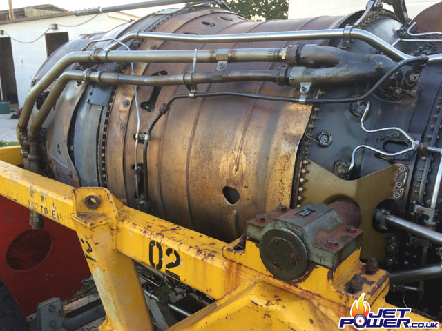
As there is not an afterburner attached, the feed pipework can be removed and blanked, pictured are the two pipes that can now be removed from source.
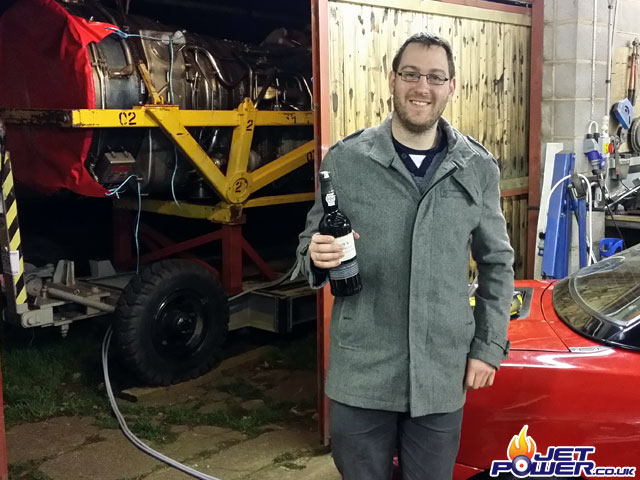
Jon Starr and his bottle of Port, its always civilised to have a tipple when working outside in December.
Patching of the electrical terminal box is coming along nicely.
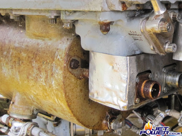
There are two HP Fuel valves on the Olympus, one of them for some reason is very corroded, although the contacts themselves seem to be in fair condition. The throttle actuator which is located behind it needs to be removed and de-engineered if possible.
A view of the throttle control input shaft with the actuator removed.
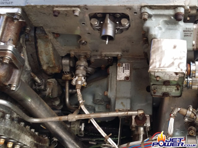
A close up of the throttle control input shaft.
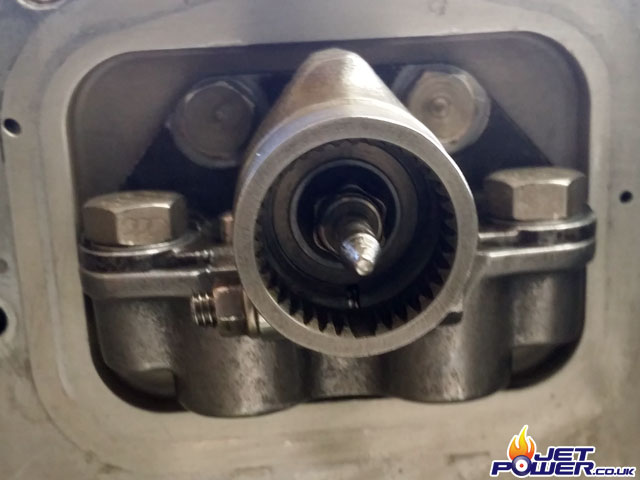
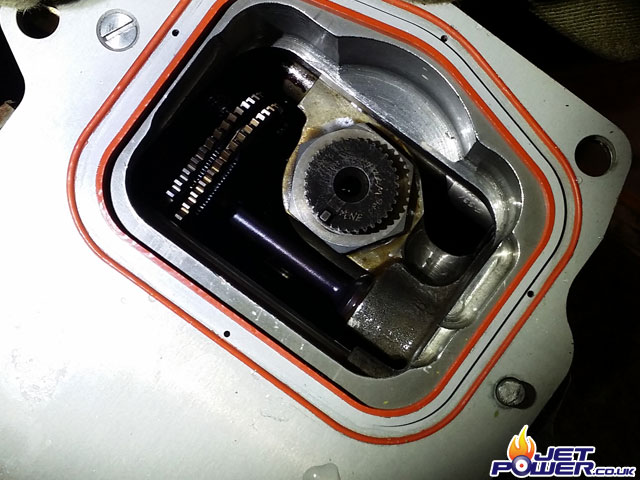
A view of the removed throttle control actuator drive mechanism.
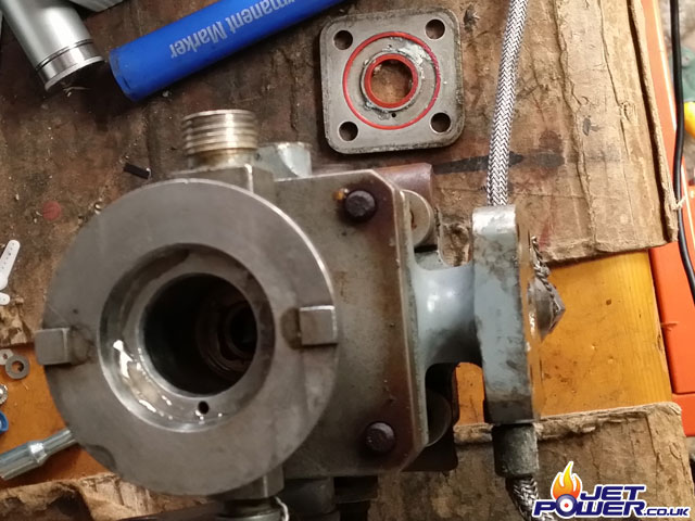
One of the many fuel solenoids that have suffered from water ingress.
A strip down and a clean in the ultrasonic bath will help.
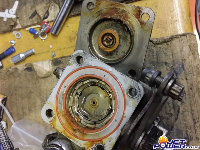
More evidence of water corrosion, these things cant be ignored, although I wish they could.
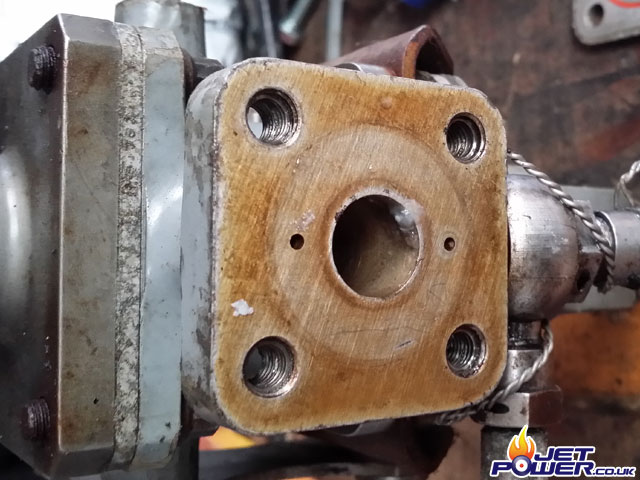
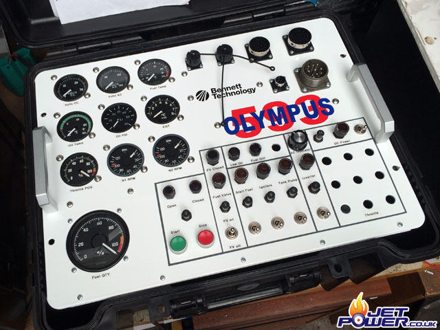
The control panel is coming along nicely, although it is a bit of a mind tease getting everything to work as close to as it would have been in the Concorde.
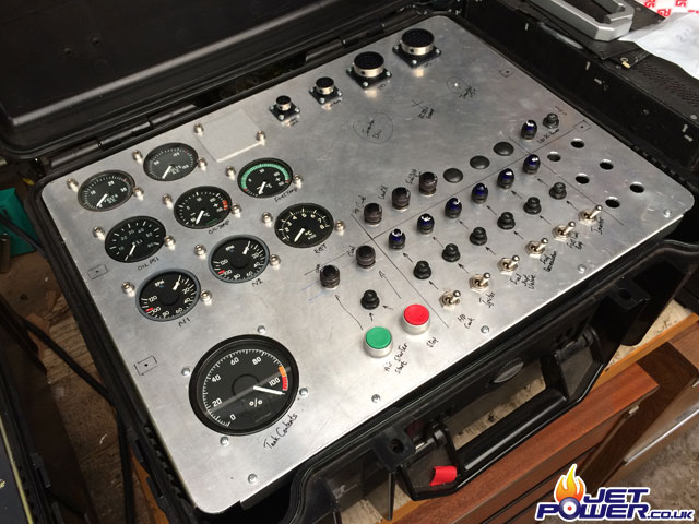
A white powder coat helps the control panel to look a bit more professional.
