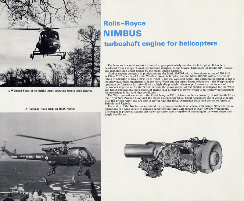
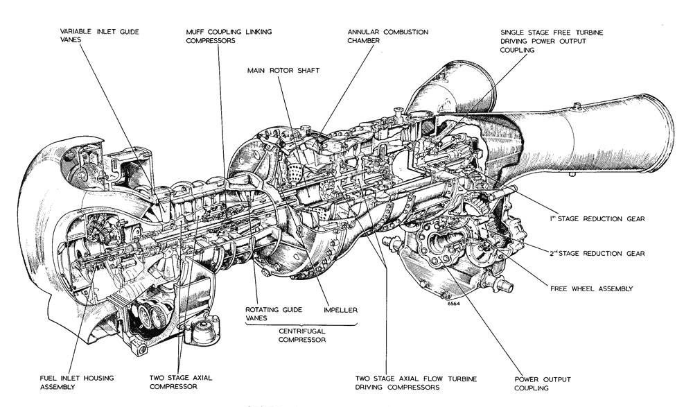
The Nimbus is a popular engine amongst collectors as there is a fair amount of them around and also fairly easy to operate.
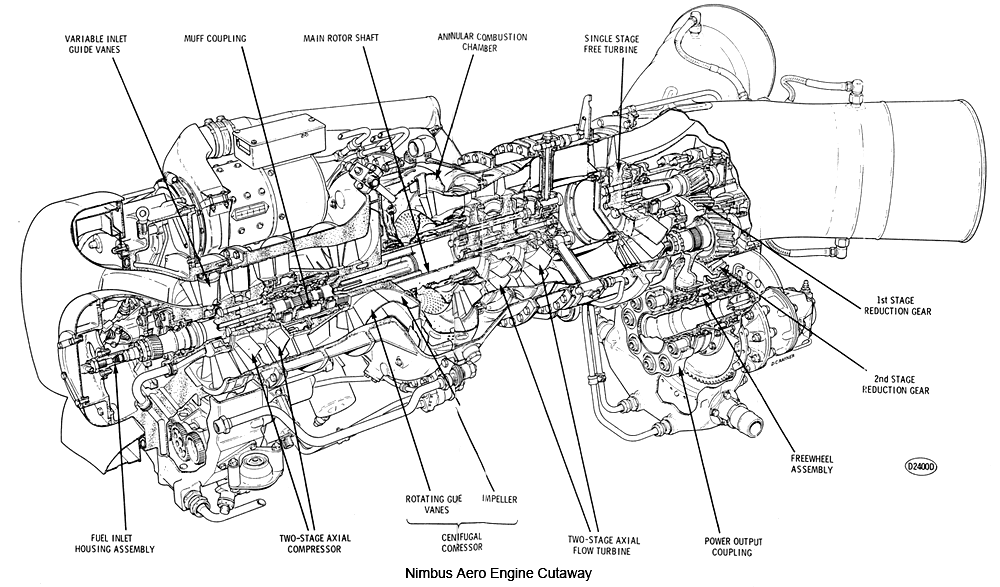
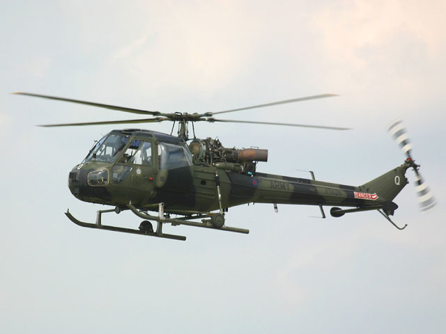
The Engine comes from a Westland Scout Helicopter, we are only going to use the gas generator section, the free running turbine mounted on the back of the engine that normally drives the rotor blades will not be used.
This is a front view of the Nimbus 503 Gas Turbine mounted on its transporting crate, as you can see the foreign object damage cover is in place, with the 24volt starter/ generator in view, top left of the engine.
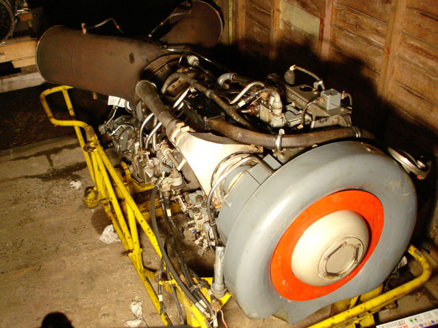
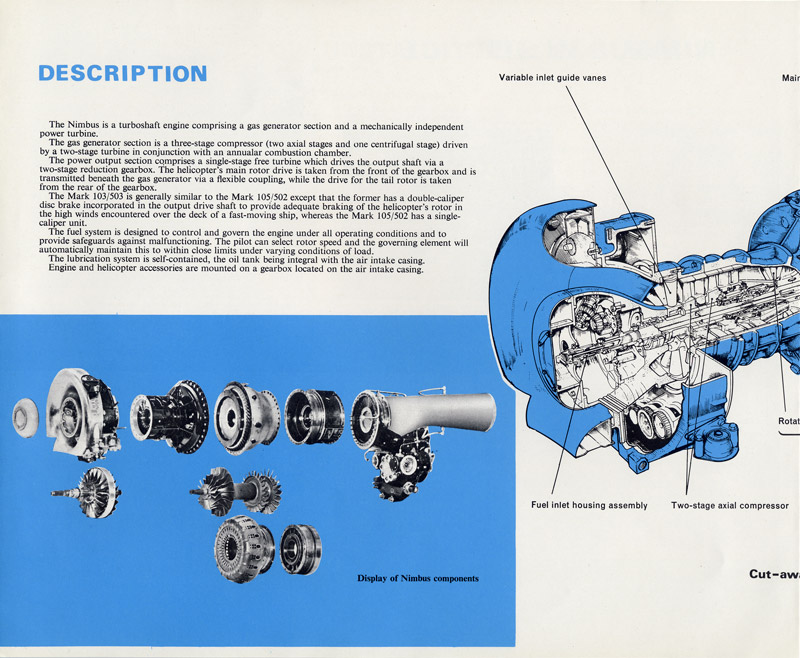
A rear view of the gearbox assembly that will not be used on the Jet Pickup. The Nimbus produces a fast stream of gas which then spins a high speed turbine wheel, which then in turn powers a gearbox (shown above) this drives the helicopters rotor blades via a connecting shaft.
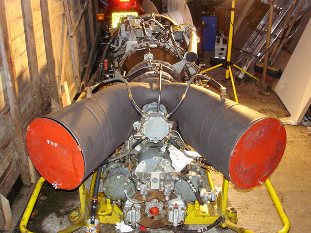
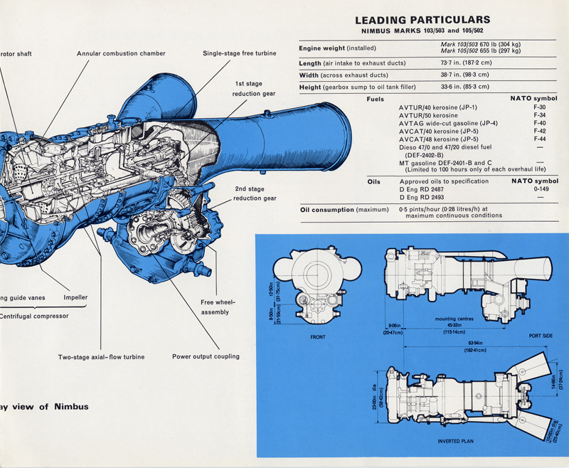
A view of the engines dispersing exhausts, with the gearbox just visible, the cables mounted on top of the exhausts are thermocouples, these will have to be removed and mounted on to the new exhaust nozzle which yet has to be fabricated out of stainless steel.
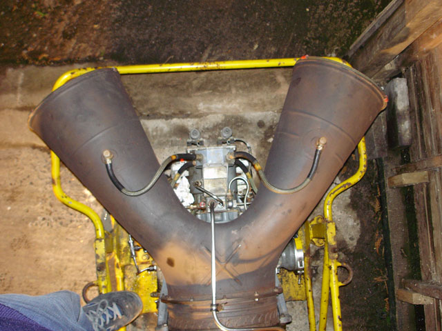
The pipe work in the midground is the engines anti-icing heating system, this of course doesn’t really need to be left installed as we hopefully wont have to worry about falling out if the sky if its cold. The theory is the less we modify on the engine the better.
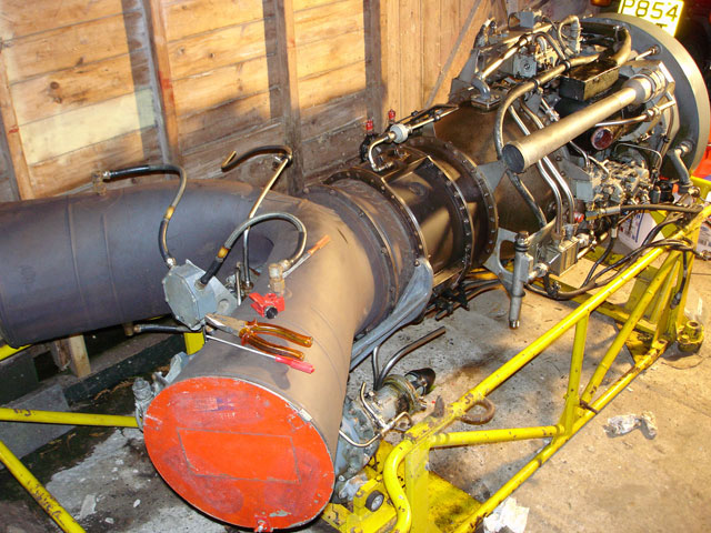
A slightly nervous bit, next time I will fabricate an engine lifting frame, though the webbing does a good job.
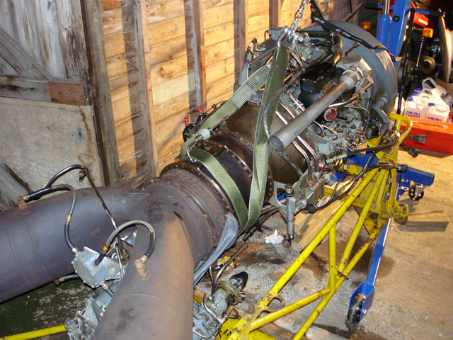
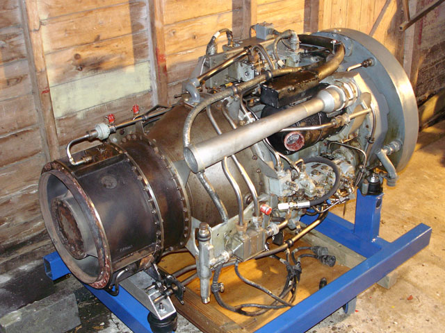
At last, finally the engine has been separated from the gearbox and is now sat happily on the blue running frame, we can now start looking at how to get the oil, fuel and electrical systems configured. Much easier to work on!
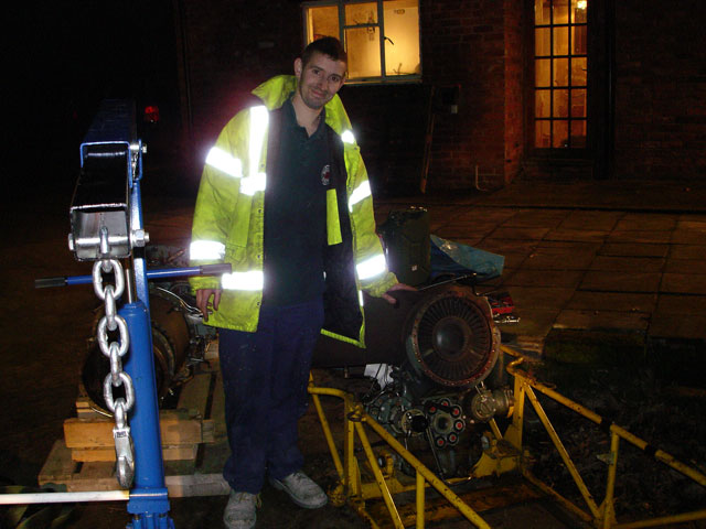
One of my friends ‘Rob’ who has kindly given lots of his precious spare time to this project. Here he can be seen with the separated gearbox/ exhaust assembly. The gearbox rotor drive can be seen below the free turbine inlet.
We are now looking straight up at the exhaust bearing housing with the cover plate removed for service access. While the plate is removed, I am going to drill a hole in the middle of the plate for the exhaust spike to be attached.
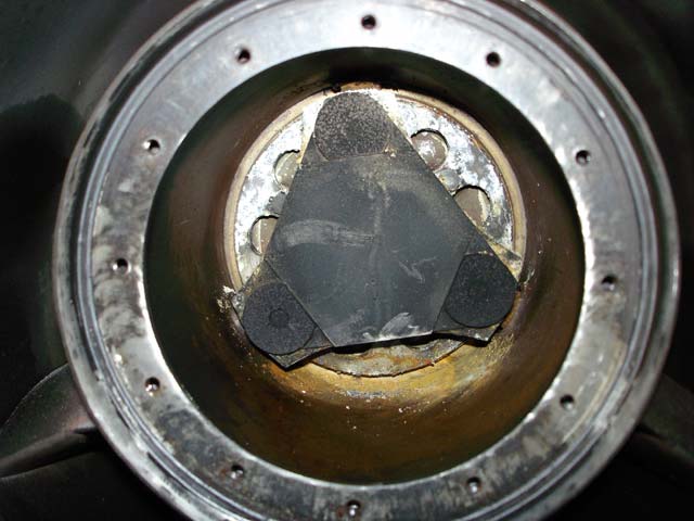
The plate has now been drilled with a M10 hole and a nut welded to the back, there was however slight warping to the plate, as there is plenty of clearance this should not be a problem for the snug fitting of the exhaust spike.
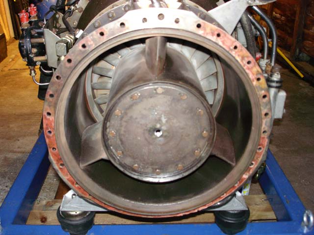
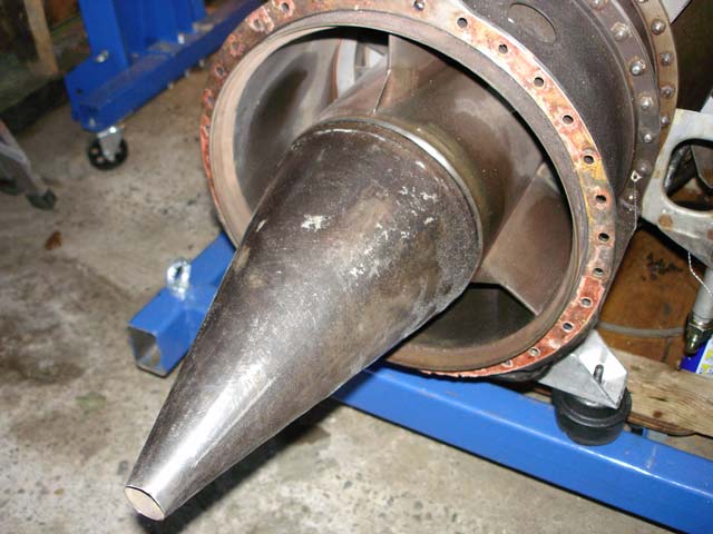
There we go spike attached, just needs to be torqued up now. The spike comes from a Artouse APU and has the same fitting on the housing as the nimbus. Time to get the exhaust nozzle fabricated out of stainless steel. Also I better have a go at getting that old gasket paper removed.
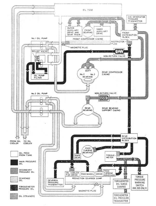
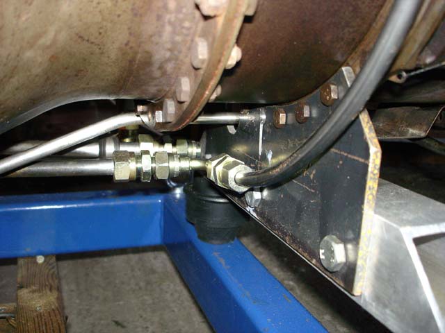
Now that the gearbox has been removed, it’s time to have a go at the oil system. I intend to reroute the oil rather than just blank of the supply feeds as done by other turbine enthusiasts. A temporary oil pipe has been connected where the oil cooler will be mounted, shown bottom left.
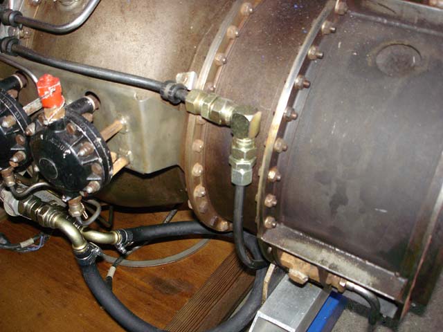
This shows the oil feed coming down from the top right of the picture and connecting directly in to the gearbox scavenge pipe work. As the 2 scavenge pipes run in parallel, one can be blanked off without any concerns of back pressure.
The Oil Cooler has now been fitted to the left side of the engine frame, mounted on four shock mount rubbers which are bolted in turn to a piece of aluminium angle. A piece of stainless steel grid plate makes an excellent protection cover as the oil cooler is quite fragile.
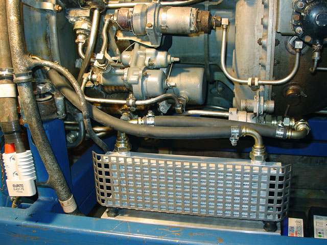
We decided to cross the pipe work so that any vibration coming from the caddy pick up or indeed the engine will be dissipated. To do this I removed the steel oil return pipe which connected directly to the oil reservoir and replaced it with the rubber oil pipe that can be seen in the foreground.
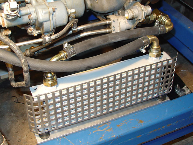
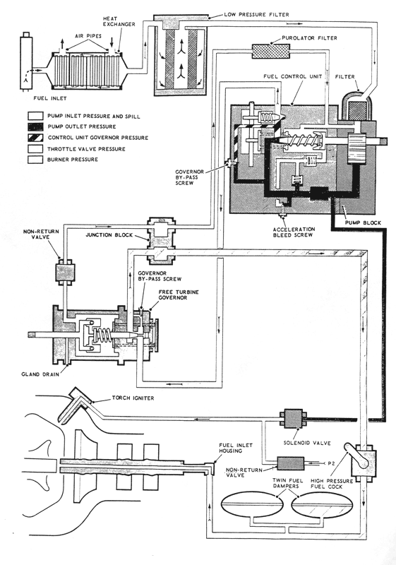
This picture shows the high pressure fuel system. Normally the engine is governed by the free turbine section, but as it has been removed, the fuel pipe work can be connected directly to the HP shutoff cock shown at the top left of the picture. To make shutdown easier, I have also added an electronically controlled fuel shutoff solenoid valve, shown bottom center. The fuel pump is to the right.
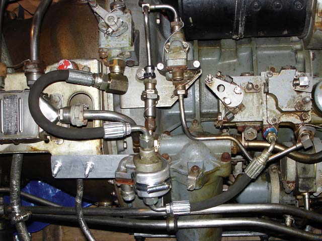
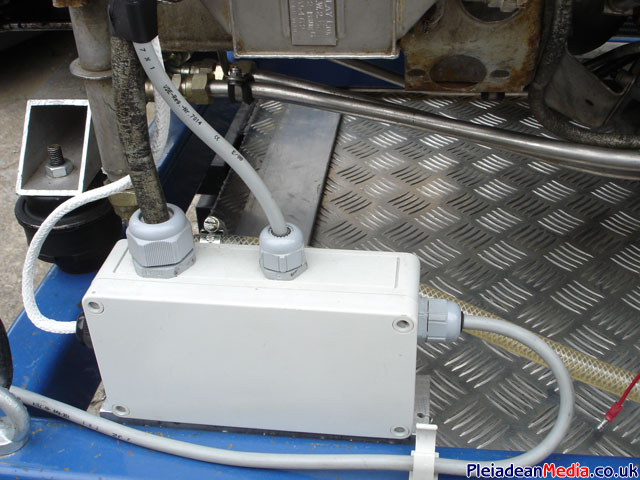
With the free running turbine now redundant, the loom that connected to it has now been cut off and terminated in a Hermetically sealed box! Makes the wiring a lot neater to look at.
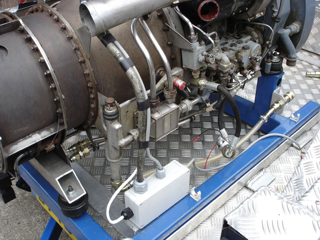
From the left – Thermocouple, Nimbus Wiring Loom, 24 Volt Supply and cable which at some point power a fuel priming pump.
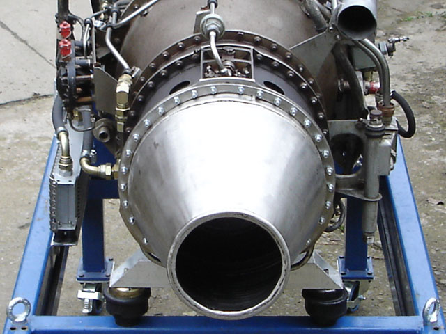
The exhaust nozzle is made from 3mm stainless steel, on the thick side but it will do the job.
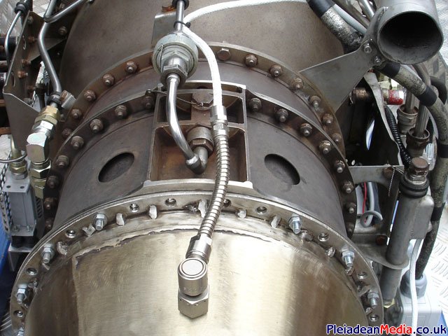
A picture showing the Thermocouple in place. I suspect the it may be a little to close to the gas generator section and may need spacing out a few inch’s.
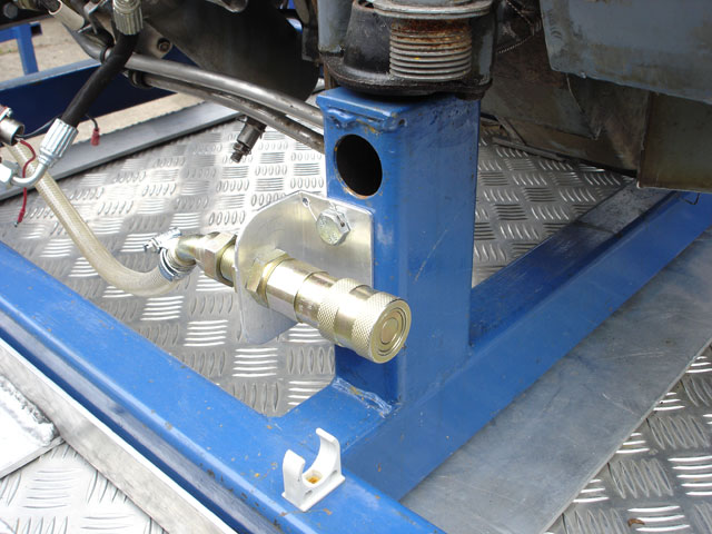
1/2″ Quick Release Connector for the fuel supply. Things like this make mounting and removing the Nimbus a breeze. At the moment I can mount the Nimbus on the Pickup and connect it all up within 3 minutes, not that time is really an issue.
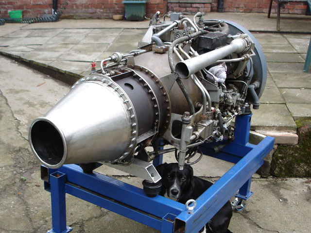
Engine frame and transport trolley.
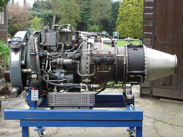
Side profile of the engine, pretty much as it will be seen on the back of the pick up. With some polishing of the aluminium and chrome parts that are already on the engine and a cleanup of the cabling, I’m hoping that the engine will be a eye catching thing of beauty!
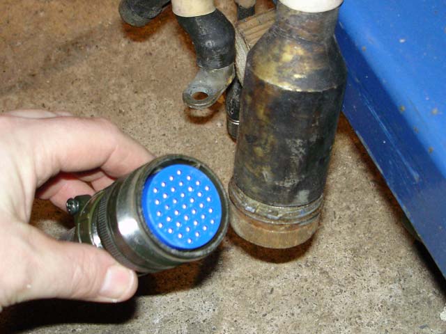
These interface connectors for the Nimbus are harder to get hold of than you can imagine, they are full military specification and built to last, not cheep but worth every penny. I better start thinking about the electrical side of things.
Today was the day I was going to have the first dry run of the engine, just a turn over with no ignition, what could be simpler? Great news, it won’t turn over! just my luck. I had the batteries checked by the supplier and they were fine, so it must be the starter, time for a look at its electrics.
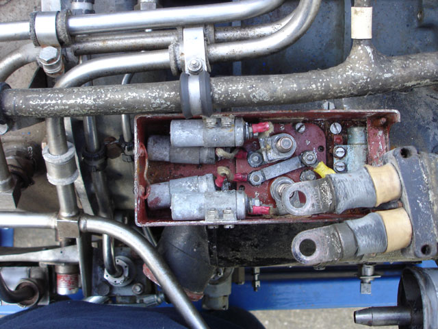
This is what the starter looks like when removed from the engine. It will need a sand down and a coat of paint for cosmetics, apart from that the construction seems to be sound.
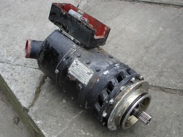
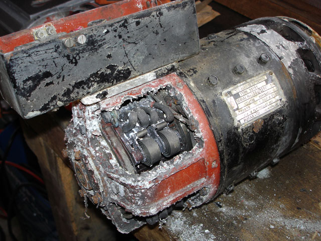
I have done a test of the starter and it is definitely faulty. At a guess the Armature coils are shorting, as the starter will not turn, even when removed from the turbine. This is very strange as it appeared to be working fine when I first purchased the engine and as this is the first time some volts had been put through it since then, I’m left clueless as to why it has developed this fault. The debris you can see is paint that has peeled off from 30 years of use.
Thanks to James and Richard Everett for being my saviors! A couple of nice blokes from Ipswich, they had a brand new armature in stock for my 30 year old Rotax Starter, surely that’s got to be a bit lucky! Have a look at their web site located at www.everettaero.com
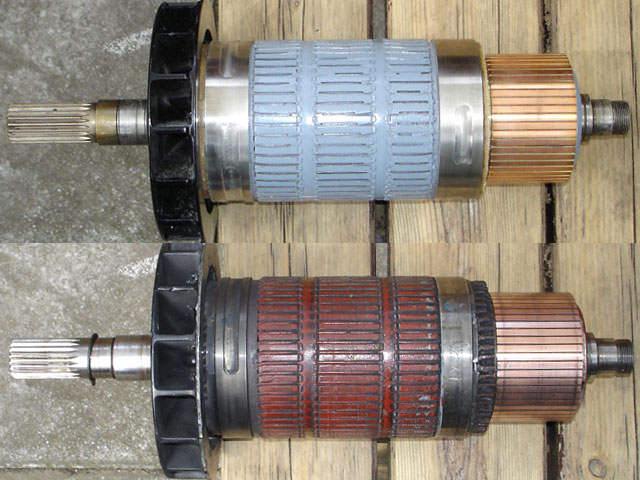
Pictured above are the 2 Armatures, old and new.
Ray Jones of Snailbeach has now put the starter back together for me, now its time to get on with the electrics.
