I only have the gas producer section of this Solent, so it seems a Turbo Jet is the way forward for this ex Phantom APU.
The Plessey Dynamics Solent ‘Gas Turbine Starter’ or GTS were used for the starting of the Rolls Royce Spey engines on the British F4 Phantom Fighter Aircraft. They have in recent years become extremely popular for projects like this as with the gearbox attached they can produce up to 70 SHP, pretty good for its size.
This is pretty much how the Solent was when it was delivered. As you can see the Free Turbine has already been removed, with the idea of making this Solent a small but powerful Turbo Jet Engine. The engine came from a genuine Rolls Royce Engineer who also collects Large Gas Turbine Engines. An active link to his website (terrafirmajets.co.uk) can be found on the links page of this Website.
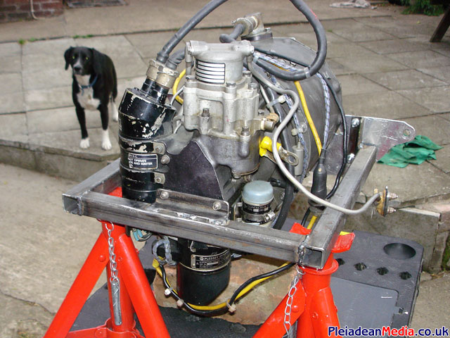
Left hand view of the engine with the fuel pump shown on the upper left hand side of the picture. A mounting frame is the first job so that it can be worked on with out getting damaged.
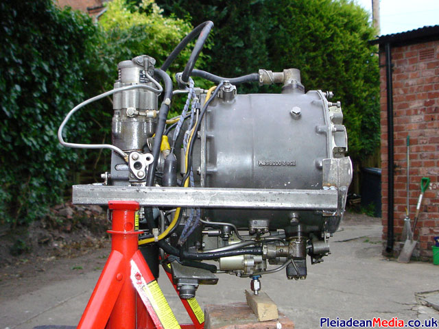
Right hand view of the engine showing the Igniter box upper right of the picture and the 60 second one shot oil system which can also be seen centre bottom, this will at some point be converted to a electronic oil feed for continuous operation.
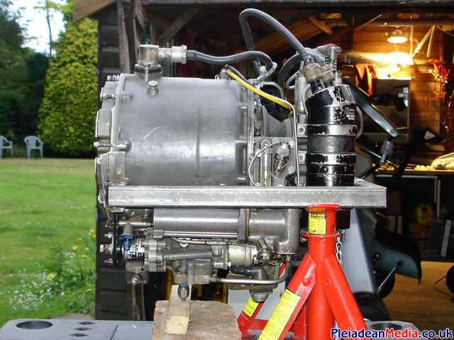
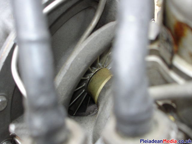
Front view of the compressor wheel looking over the Igniter box. The starter and fuel pump connection coupling (in gold) can be clearly seen in the centre.
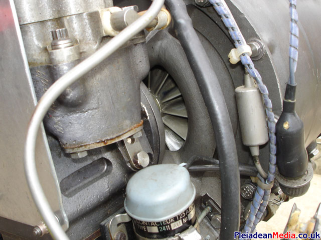
Another view of the compressor wheel, but this time from the right hand side. The R2D2 box at the bottom is the starter solenoid.
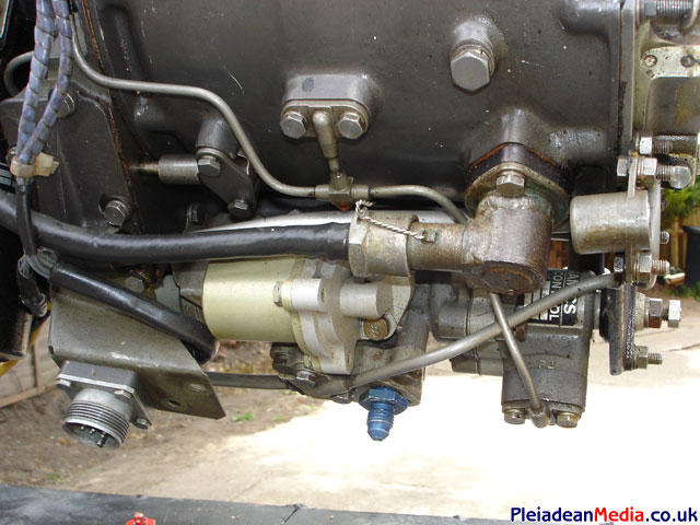
Close up view of the electrical buss connector, the Igniter plug, back of the oil feed system and fuel supply fitting.
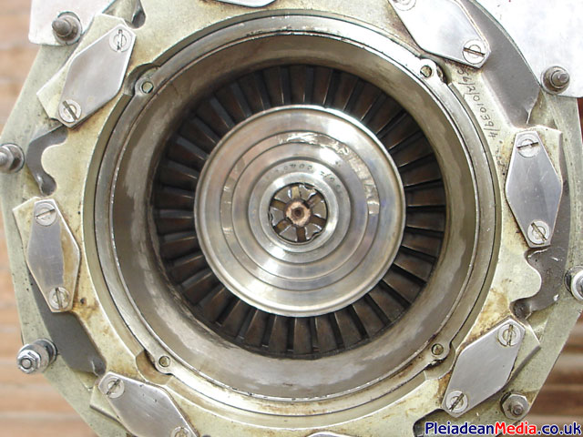
What a beauty! The turbine wheel is truly fantastic piece of engineering. I will have to make a substantial exhaust nozzle to do the Solent justice.
Re Think Time!
I have now decided to remove the Starter, Fuel & Oil Systems which has reduced the weight of the unit by almost 50%. Starting will now have to be by Model Aeroplane Starter or possibly a Leaf Blower. Pictured is the Solent with all ancillaries removed.
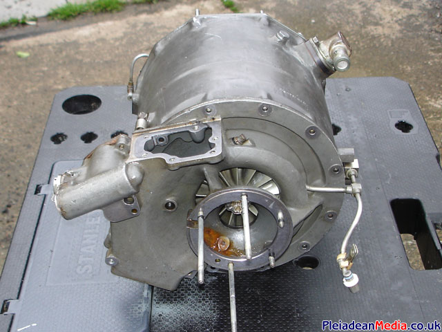
Front view with bits removed. Engine is now lying on its right hand side.
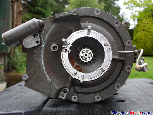
In this picture you can just about see the oil reservoir as the cover plate has been removed. The engine is now on its left hand side.

A close up of the compressor nut and wheel. The front part of this casting will have to be machined away so that an air tight seal can be made if using a leaf blower to start. Also a Spinner Nut will have to be fabricated to replace the one used.
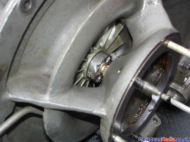
The front of the Solent with the front casing removed. The Compressor wheel is now clearly shown, if you look carefully you can see the balancing grinds on the outer of the wheel.
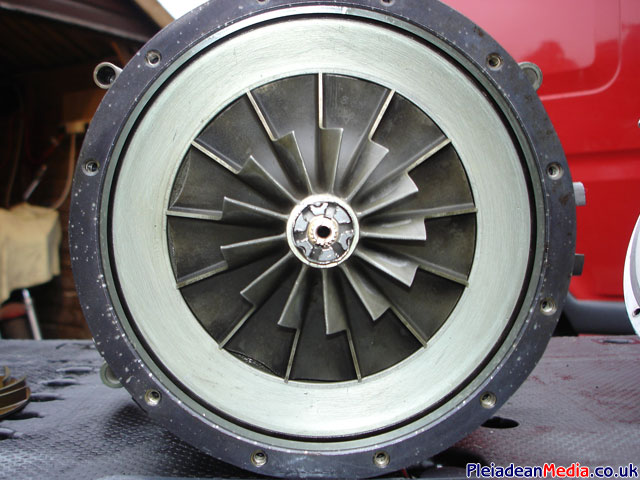
The Diffuser removed, this surrounds the Compressor Wheel.
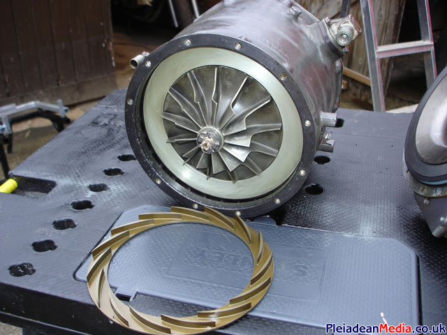
A picture showing the inside of the front casing. The gasket that can be seen on right hand side is where the ‘One Shot Oil’ tube is attached.
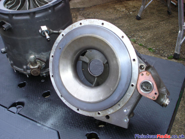
Front Casing and Main Body.
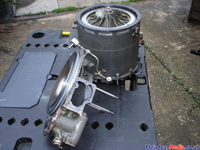
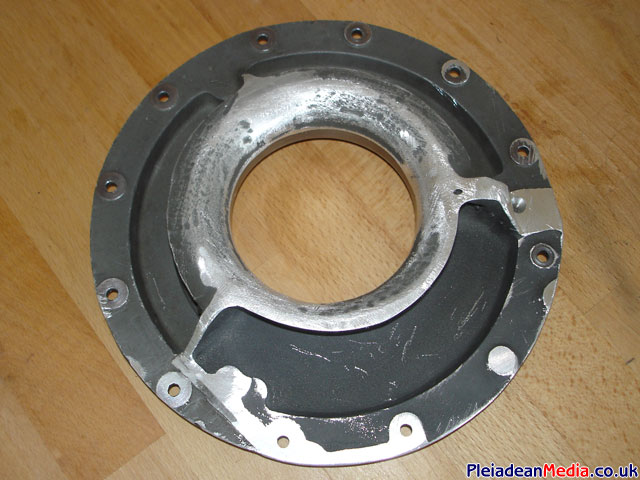
The Front Casing Before Milling.
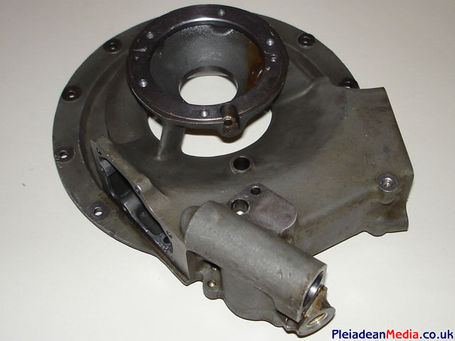
The Front Casing After Milling.
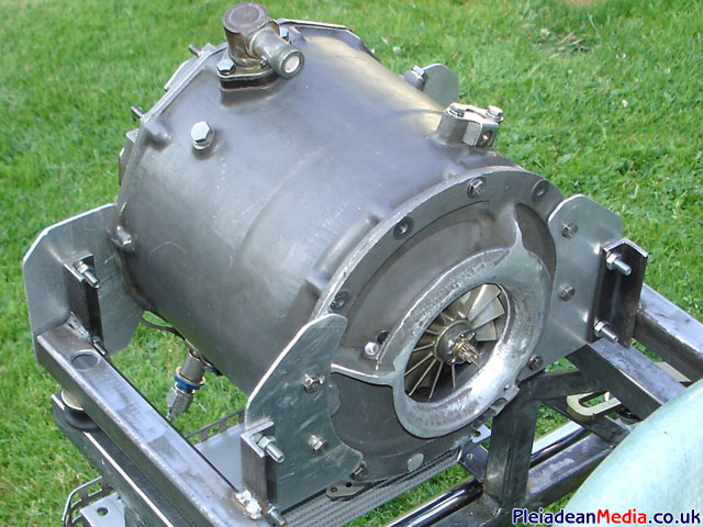
View of the front of the Solent which has now been mounted on the front using aluminium panels. A small aerodynamic spinner nut will also have to be fabricated, this will have a reflective strip on it for the Laser Tachometer so I can keep an eye on the RPM when in use.
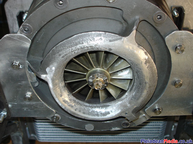
At this stage the plan is to start the engine by air from a Leaf Blower as there is not enough room for a hand held electric starter between the seat and the engine. Note the paint has had to come of the frame as I found out that Kerosene melts paint and makes it all very sticky. Which was nice.
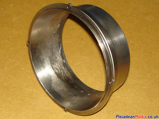
This is the Exhaust insert that would normally connect directly to the Free Running Turbine. The exhaust cone that I am going to have to fabricate will attach directly to this. This is a small issue as its normally the FRT that holds it in place, so an external bracket of some description will have to be made.
A view of the Solent with the Burner Ring removed. The Combustion Chamber is now clearly visible, showing the eight fuel inlet holes.
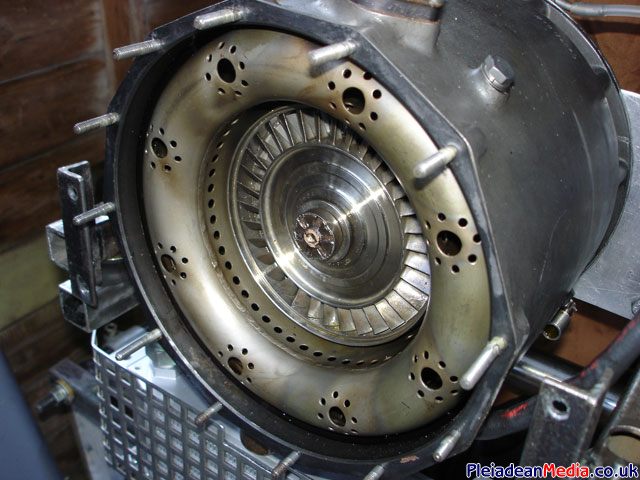
The Burner Ring, with its eight Injector nozzles can be seen here. The way the Solent normally works is that the Injectors work in pairs for smooth starting. 2 for initial ignition, then 4, 6 and 8 at full throttle. The fuel flow is governed by a device which takes air pressure readings from the case to work out the RPM.
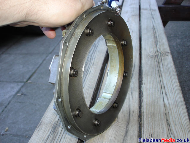
Time to calibrate the Simplex Fuel Nozzles. I made a clear test rig using a gold fish bowl with the burner ring mounted on the top, the idea being I could see the nozzles and check at what pressure fuel was injected and how well it was being atomised.
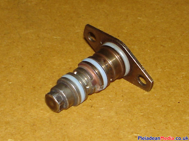
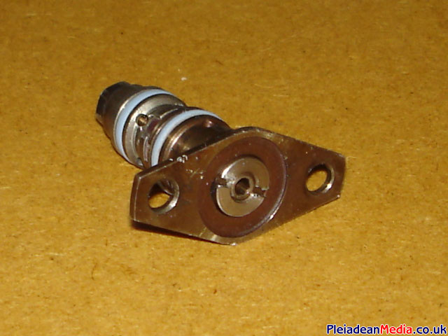
Here we go again, 4 out of the 8 nozzles don’t work. I’m going to remove them all and see if they are serviceable. Pictured above is one of the 8 Simplex Burners, the allen key adjustment screw with the locking ring around it can be seen in the middle. Hopefully some oven cleaner should remove any carbon deposits that may have blocked the injectors.
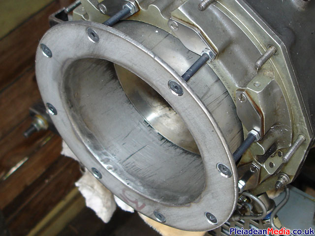
The start of the exhaust assy. A piece of stainless tube witch is machined so that it fits the face of the Solent’s exhaust insert. To this I welded a flange. The fuel ring injectors threads were then re-tapped and coiled to an M5 Thread, (easier than the 5/32 that it came with). The flange is bolted in 8 places now by M5, 50mm countersunk bolts. This means that without a lot of hassle I can experiment with various sizes and shapes of exhaust nozzles.
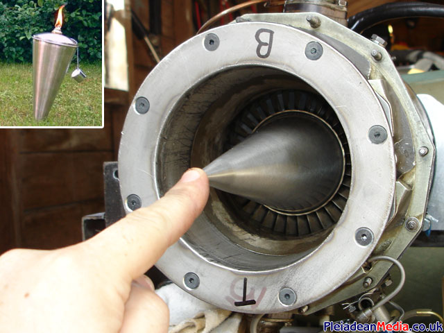
The base of a garden paraffin lamp is going to form the exhaust spike. I am going to weld some stainless penny washers in the middle of it to stiffen it up and then weld it to the exhaust assembly. Time to make one of the exhaust nozzles I guess.
As they are fairly new and shiny, I thought you may like to see a picture of the custom HT cables I have made up. They look a lot better than the old ones which also had insulation problems.
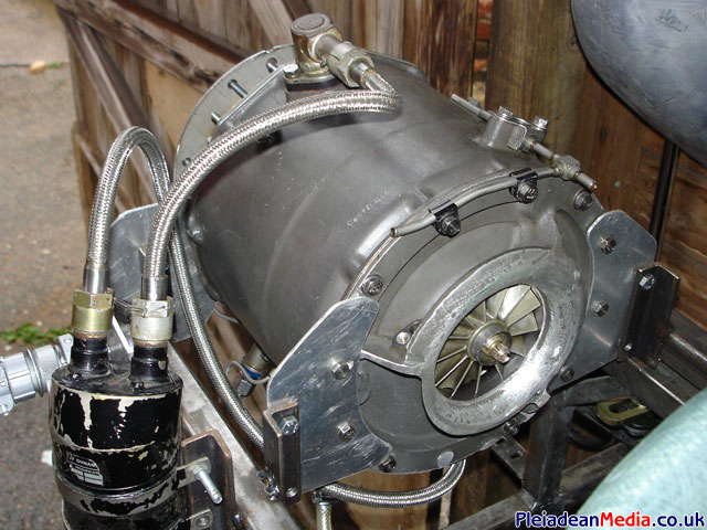
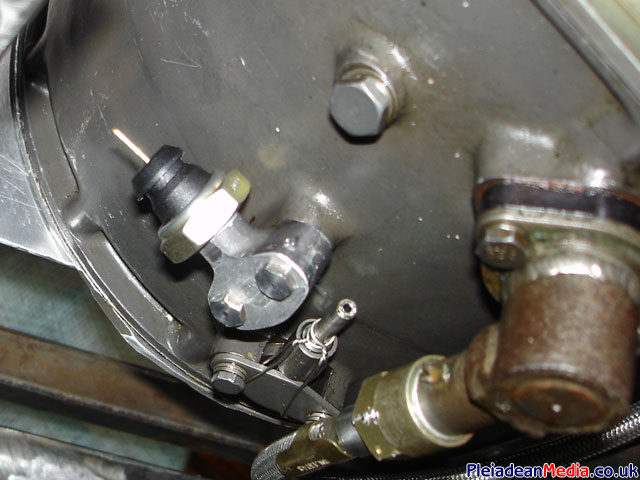
Start of the new oil system. I soon realised that when making test runs I was turning the oil pump on to early, resulting in dangerously high exhaust temperatures. The reason for this was that the bearing seals partially rely on case pressure to keep the oil in its place. Without this gas pressure the oil leaks out and gets burnt. I decided to use a 20 psi VW oil switch, which when activated due to sufficient case pressure, will energise a relay which will then in turn power the oil pump, providing oil pressure as and when required.
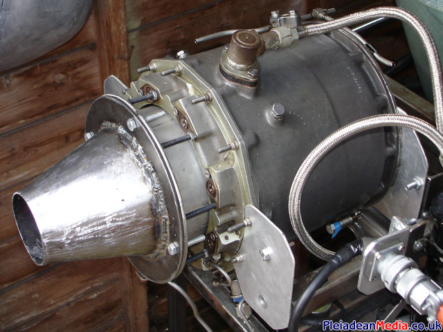
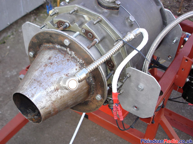
First of the experimental exhaust cones. This one has an exhaust diameter of 125mm down to 65mm, which is as small as I expect the Solent will operate safely with. If it grunts a little to much with this, then I can always open up the nozzle some more. Thanks again to Tim Jones for rolling the tapered nozzle.
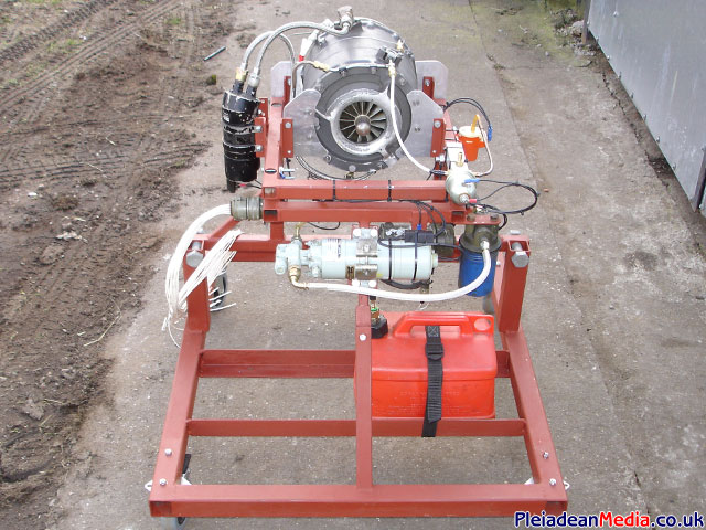
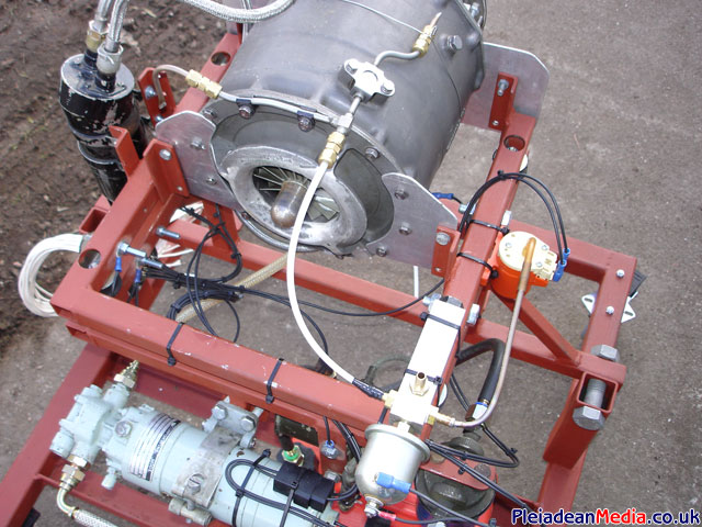
I decided that trying to get an engine running from scratch and fitting it on a Kart at the same time was making trouble for myself, so I have now made a running frame, similar to the one I made for the GTP30. This makes life a lot easier for the initial setup as my main concern is to get the Turbine running safely first.
A view of the QR Electrical Connector which I managed to salvage from the chassis of the GTP30 GPU. This was a blessing because these connectors aren’t cheap.
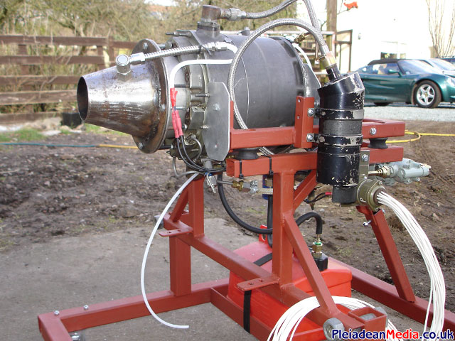
A view of my wiring harness that connects to the required electronics. 1: Oil Pump, 2: Oil Pressure Gauge, 3: EGT, 4: Tachometer, 5: Igniter Box, 6: Fuel Pump, 7: Oil Pressure Pump Activation Sensor, 8: Priming Fuel Pump.
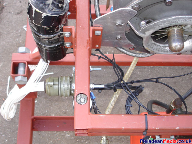
The K Type Thermocouple is now mounted on the exhaust nozzle, I just need to fix the wiring securely.
Start of the oil feed pipe work. I was initially going to use a PAS Pump form a Peugeot 106, but I felt after getting one it was just to big for this project so I have now gone back to my Model Helicopter refueling pump. The line will be Tank, Pump, By Pass Valve with Sender and then the Solent. It will be scavenged from the bottom, then straight back to the reservoir tank.
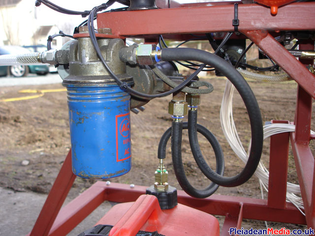
Fuel system, consisting of parts scavenged again from the GTP30. The fuel flow is Tank, Priming Pump, Fuel Filter and then the HP Fuel Pump.
Constant Run Test, Hot Start – I need a slightly more powerful fuel pump so that the nozzles can be closed down for a better spray pattern. (35lbs Thrust). Tweeking needed.
Diesel Fuel Test, Engine runs better on Parafin, diesel runs to hot.
(24lbs Thrust) It even went for a walk!
