I had run out of ideas of quirky things to make and a mate of mine, Nick Roberts son Tom, came up with a Jet Powered Trunki. Seems obvious now, thank you Tom.
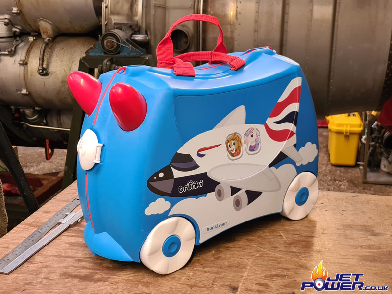
Kid’s Trunki cases are made in lots of different colours and graphics, but I felt an Airliner spec Trunki would be the logical choice to start this project off with.
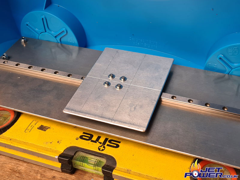
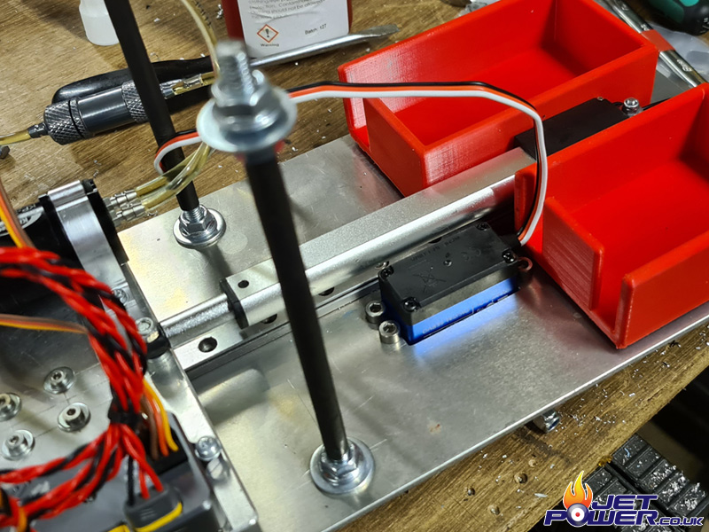
First job was to split the case in to it’s two half’s, drill the case so that standoff spacers can be added that will support the main aluminium base. The base plate will only be secured on one half of the case and just rest on the other half so it can still be opened and closed. Then I added a linear rail and bearing that will support the engine etc.
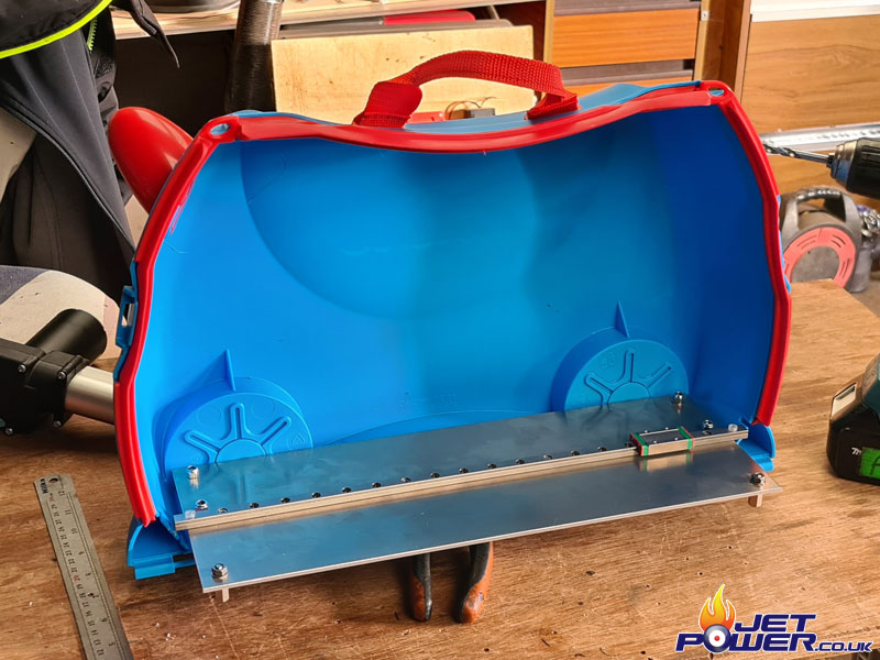
Sliding bed for the engine mounts.
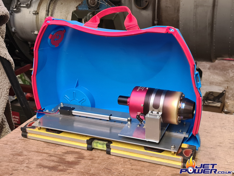
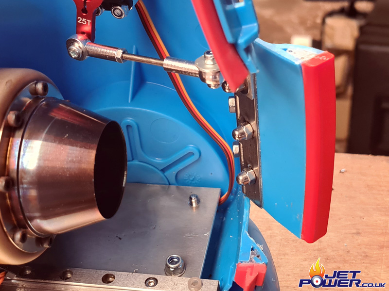
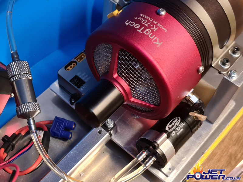
Engine support mounts fitted along with the engine of choice, a Kingtech K70G4 Micro Turbine. To partially move the engine out of the case when in use, I have fitted a 100mm linear actuator which operates from 9 to 12 vdc.
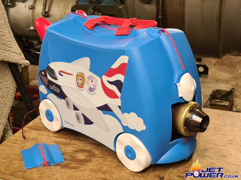
I cut a hole in the back of the Trunki to allow the hot section of the engine to poke out. I now need to work out a pivoting action for the cut out panel to open and close, depending on the engines position. Maybe I should have given this a bit more thought before the hole was cut..
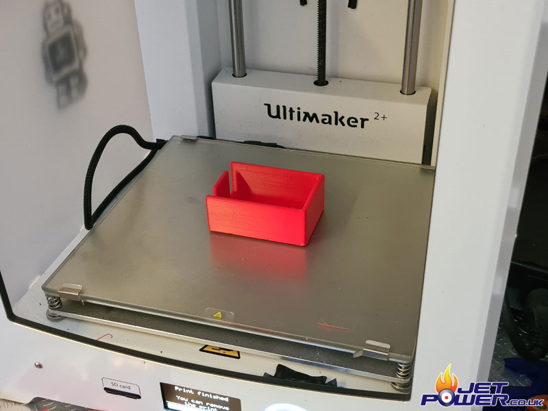
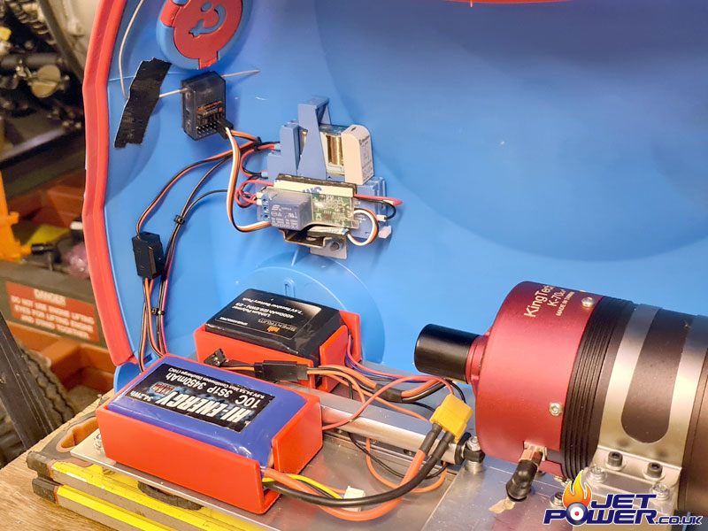
The radio receiver and engine battery holder, this will stop the battery’s rattling about when doing 100MPH when you are late and in a rush for the plane.
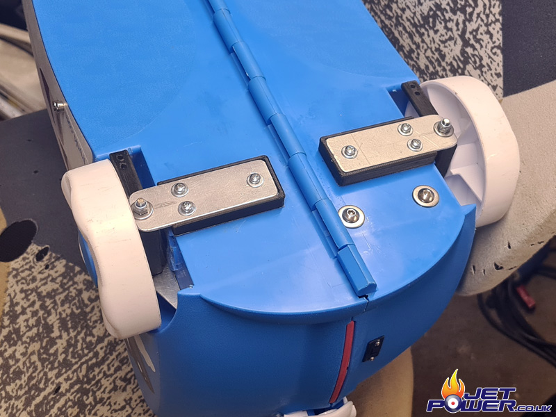
Turbine door hinges added to the Trunki utilising fitted stainless steel piano hinges. This was a little bit of a pain as the Trunki is curved and hinges don’t like to go around corners down their lengths, so I heated up the plastic of the case and doors with a hot air gun and clamped two pieces of metal either side of the edges flattening them where the hinges were to be placed and left until cool. It worked a treat, but there is now some distortion in the doors, but it still looks pretty good.
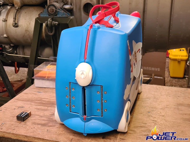
The red seal where the doors met was a pain ITA to get back in to place and secure without them wanting to fall off, so I made a bit of a guess on dimensions and 3D Printed a couple of curved inserts and glued them in to place to fill the gap.
Radio gear installed for the linear actuator.
Spektrum RC receiver is connected to a PWM RC Switch which when energised turns on a DPDT Relay that will either make the actuator extend out or retract. The same receiver will also control the throttle of the engine amongst other things 🙂
Now for the air intakes..
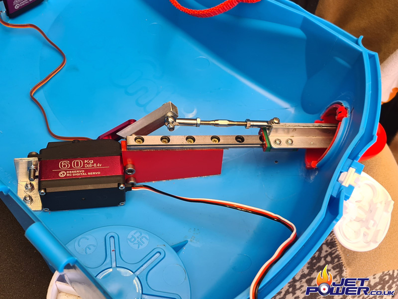
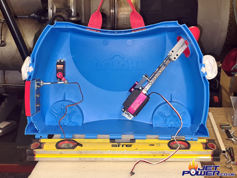
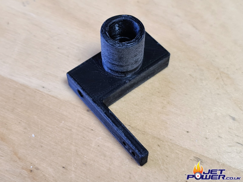
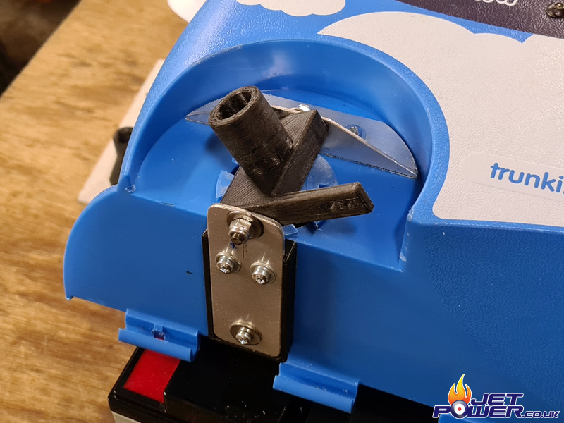
I utilised what I beleive are intended to be Trunki’s handles, rather than being fixed, they now move in for when the engine is running to allow air flow in to the case and move out when the engine run is completed. A Servo connected to a Linear Slide Rail with a Con Rod allows this to happen. The angle support for the rail was of course 3D Printed.
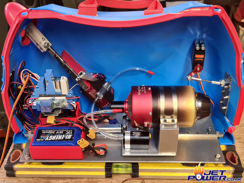
A full view of the opposing side of the Jet Trunki.
I attached the engines DRM and Fuel Pump to the engine trolley, Fuel Feed, Power and Throttle Signal will have to have to be slack to allow for the engine actuated movement in and out.
The case is now starting to fill up. I had to make a Radio change from the Spektrum to an FR SKY Receiver as the Spektrum was problematic with the PWM Servo Switch and synchronising all of the required controls.
A short video of half of the Trunki’s working automation process.
The video shows the fuel tank now in place and how the fuel lines and respective wires act when the engine is extracted and retracted.
This is my first test of the Trunki under power, for those who don’t know, Turbo Jets lack torque and require higher RPM’s to get going, once they start it’s often very hard to stop them. In the video I try to keep the revs as low down as possible as the test conditions were not the best, thus it doesn’t take an awful lot to stop the Trunki in it’s tracks.
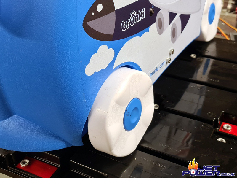
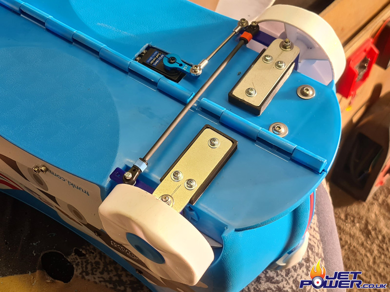
So, not in the true spirit of Trunki, I have decided to give it steering, it is jet powered after all. I designed and printed a couple of steering hubs that will accommodate the Trunki’s original wheels, with an arm for linkages to the steering servo and a central pivot through the middle.
I cut off the original Trunki stub and fabricated a couple of supports in aluminium to support the 3D printed steering hubs. I ended up using 4mm stainless bar, threaded at the ends as the pivot shafts.
To get the profiles to the correct height, 3D printed spacer plates were made to support the bottom mounts. This allows the linkage arms to move over the underside of the bottom of the Trunki.
The steering servo is now mounted through the bottom of the main aluminium plate inside the Trunki for maximum strength.
The steering servo is spaced so that when it pokes through the bottom of the Trunki only the top section of the servo is showing allowing for some ground clearance.

I cut a hole in the base and the reassembled, adding the steering linkage shortly after. I don’t get a massive amount of movement in the steering, but enough that the turning circle is about 3 meters. Due to the amount of movement, to make life more easier for me when printed the hubs, I chose not to worry to much about utilising any Ackerman Geometry.
I do try to keep these little projects as sleepers, i.e , from the outside they don’t look any different from stock, but to get the steering setup I did have to space the front wheels out about 15mm, which gives the game away a bit, I couldn’t go internal as it was already full of gubbins.