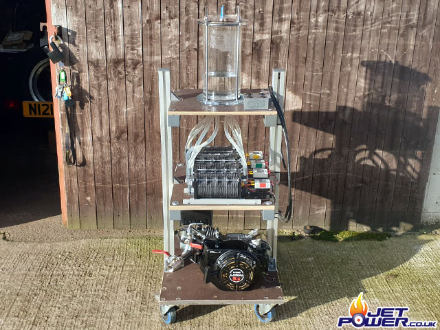
The electrolysis of water to provide a hydrogen and oxygen gas mix from which a small internal combustion engine can be run.
The start of my HHO gas producing system
(2 parts Hydrogen and 1 part Oxygen Gas)
A bank of four electrolysis dry cell modules on the bottom separately feeding the accumulator situated above. Operating voltage will be 24 volts at around 30 amps, however during the experimentation process this may well change.
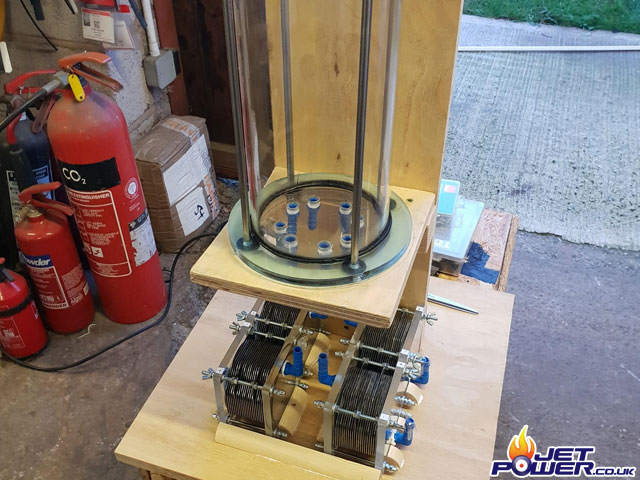
Without any form of catalyst and just running off distilled water the cells are consuming 5.18 amps at 24 volts, this will change significantly when the catalyst is added.
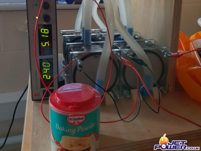
A bit of baking soda and the gas production shoots up as well as the
current consumption. However after the test I decided not to use baking soda anymore as it leaves a residue, from now on I will use white vinegar as a catalyst.
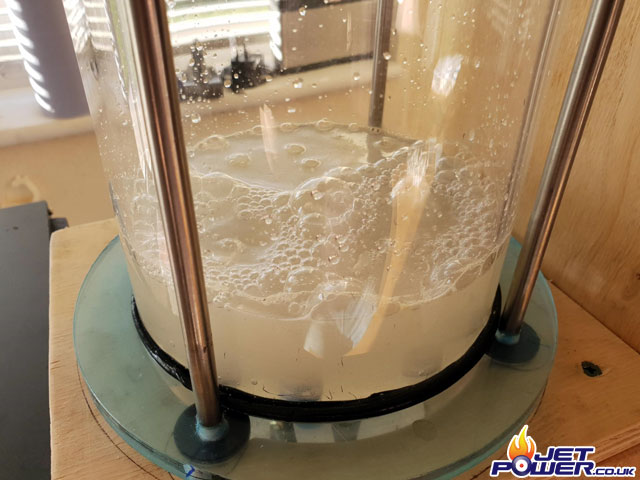
Testing with more water and outside because these things have a habit of exploding!
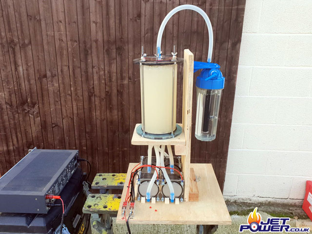
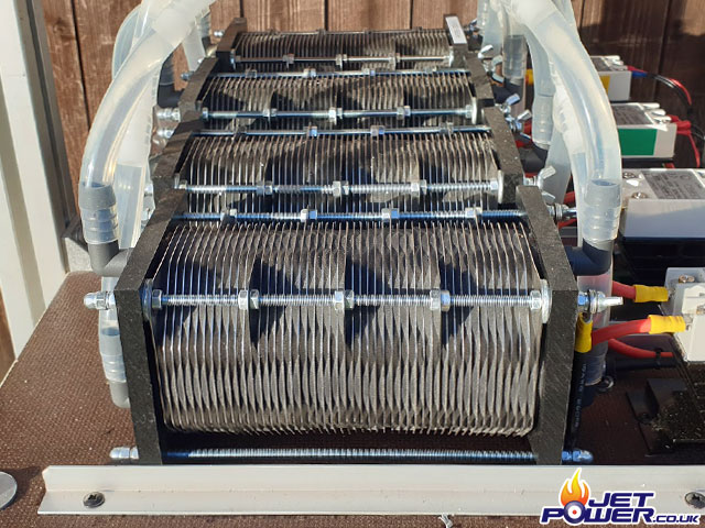
It became obvious after a small amount of testing that the 4 x 21 plate cells that I had were not going to produce enough gas. So time for an upgrade which came in the form of 4 x 49 plate cells, hopefully this should give better gas production.
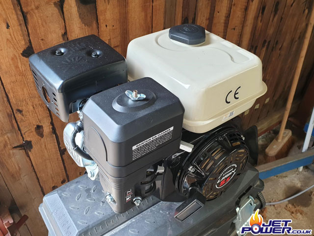
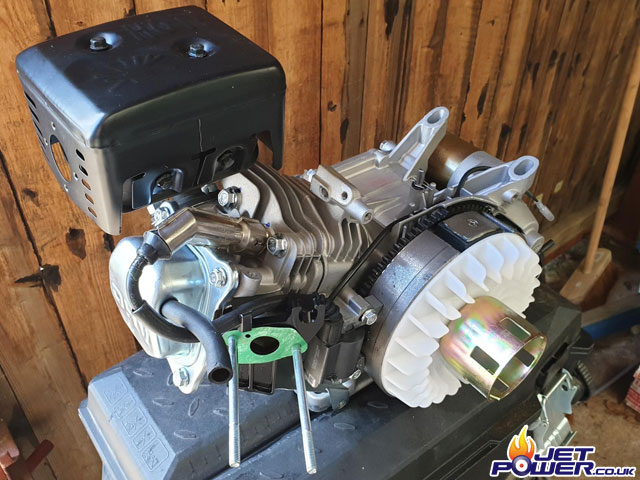
My choice of engine is a lawn mower replacement unit, basically a Honda copy, cheap to buy and thus I don’t feel so bad taking it apart to experiment with it.
Carburettor removed as well as the petrol tank and throttle assembly.
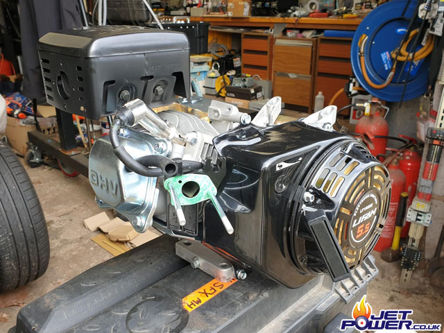
I temporarily removed the outer case to check on the possibilities of altering the timing, however it can’t stay off as it also provides the forced air cooling for the engine.
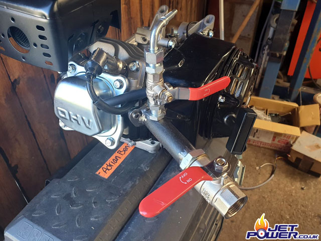
Simple carb fabricated witch will allow the basic control of air flow and gas injection.
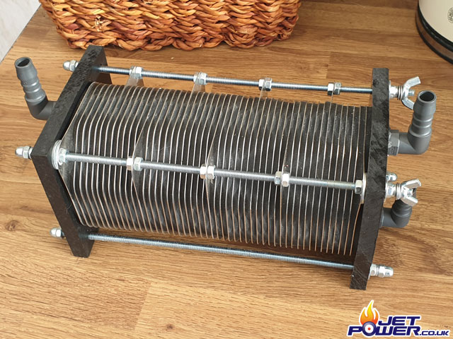
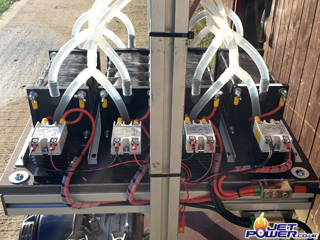
Pictured are the new replacement 49 plate cells, these are plumbed up in pairs and connected to the gas accumulator above.
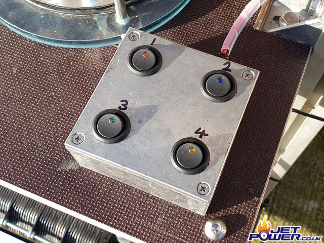
The cells will be able to be turned on and off separately by means of a solid state relay wired inline to each cell.
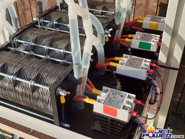
12 volts is feed to a distribution block which then feeds the separate SSR’s, the distribution block also powers the switch box which is mounted on the top shelve.
SSR switch panel.
The Humbug test rig as it currently stands.
# HHO Accumulator & SSR Switch Panel
# 4 x 49 Plate HHO Cells & SSR’s
# IC Engine Converted to run on HHO
