The plan is to put a 100HP Kawasaki ZZR600 bike engine in to a Go Kart. I can blame me old mate Phil Cred (motorcycle madman) for this one. Once the engine is removed, the remaining bike will converted to an ‘EV’ Electirc powered Kawasaki.
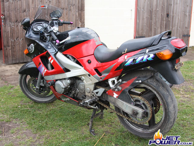
The donor bike before the removal of the engine.
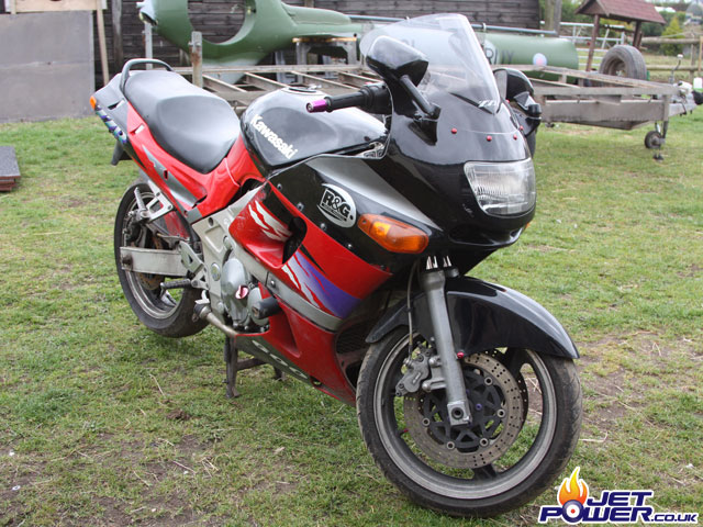
As god intended it.
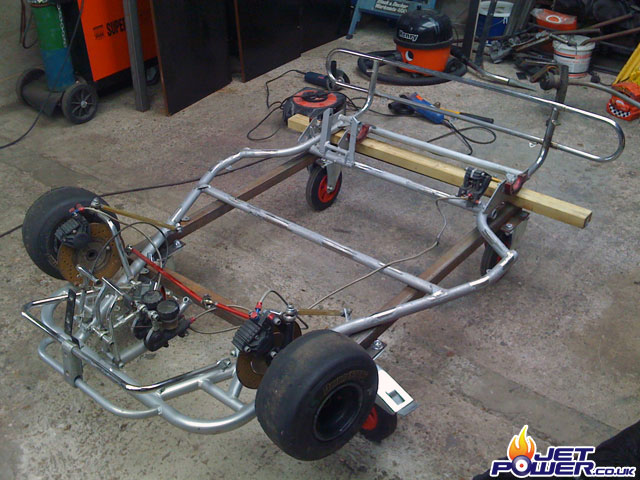
A picture of the basic Kart Chassis, lots to do, I don’t really know how this is going to work out.
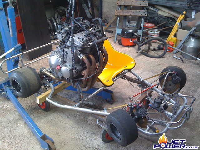
The engine was quite easy to remove from the bike, I would be stuck without my engine crane, what a blessing! In this picture I’m trying to work out where everything is going to fit.
Although not pictured, this is where I decided on how the engine mounting frame will be made.
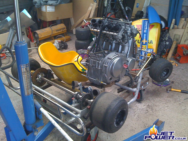
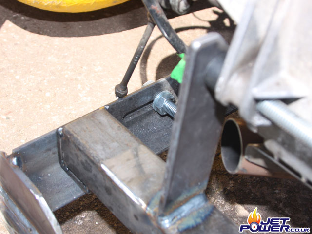
The engine frame will side in between two pieces of angle welded on to the kart chassis. The holes that you can see in the picture are part of the actual engine frame itself, these allow the engine frame to slide backward and forward within the angle frame to enable adjustment of the chain.
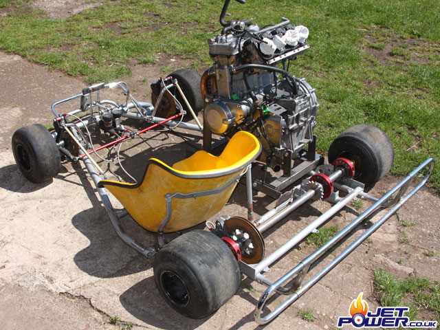
A view of the bike to help gauge whether all the parts will fit together ok.
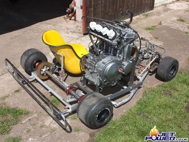
A rear view of the kart.
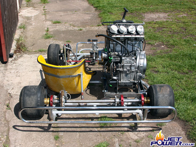
Yet another view of the kart.
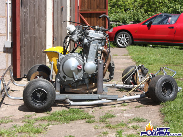
A view of the kart from the side.
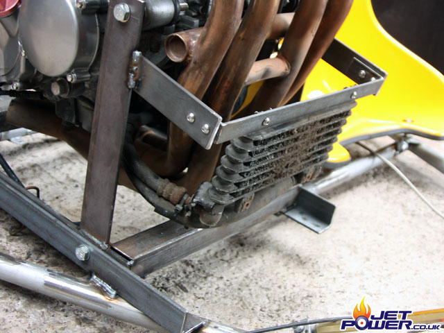
This is my first attempt at making a bracket for the oil cooler, I soon decided that it wasn’t any good and it was consequently cut off.
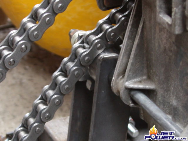
When I fitted the chain it soon became apparent that the chain just about fouls on the part of the engine casting that has the gear selector on it, thus an idle gear had to be fitted.
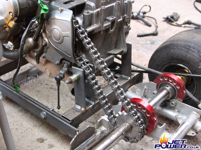
Fortunately it fits just nice inline with the rear engine mounting bolt.
Now to reinforce the standard super kart’s chassis to help support that the extra weight and horse power.
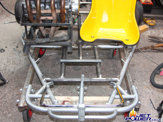
Steering mount welded in to place.
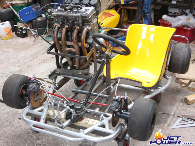
Brake pedal mount bar reinforced.
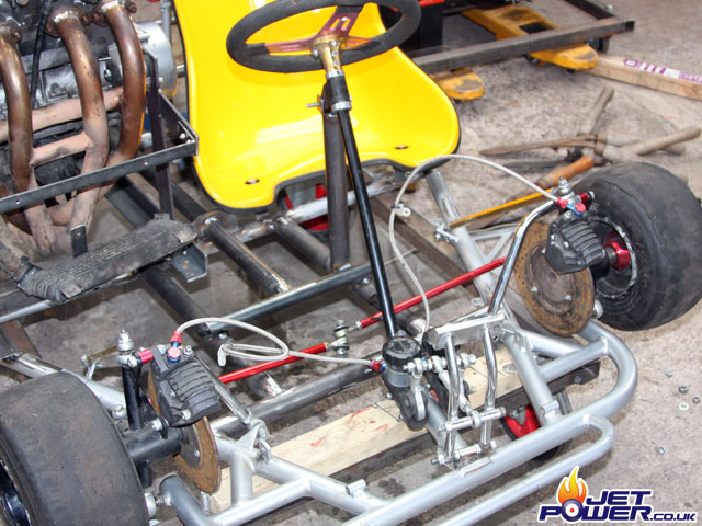
The intermediate gear selector linkage fabricated and mounted, I used skateboard bearings to reduce friction.
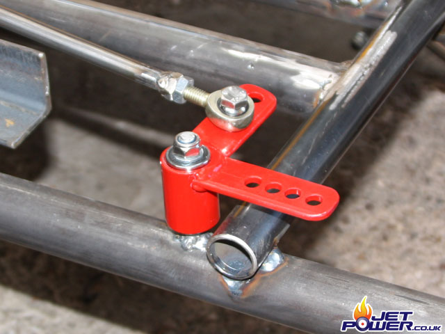
This is the linkage from the engines gear selector to the intermediate linkage.
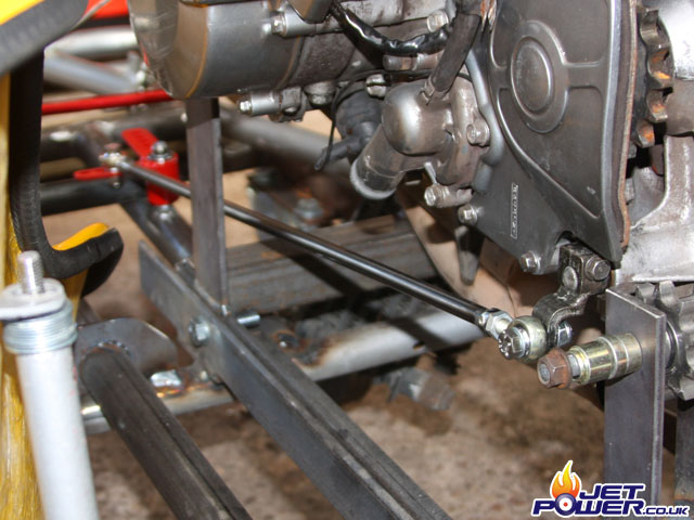
Pictured is the start of the gear lever assembly, again I have utilised skateboard bearings to reduce friction.
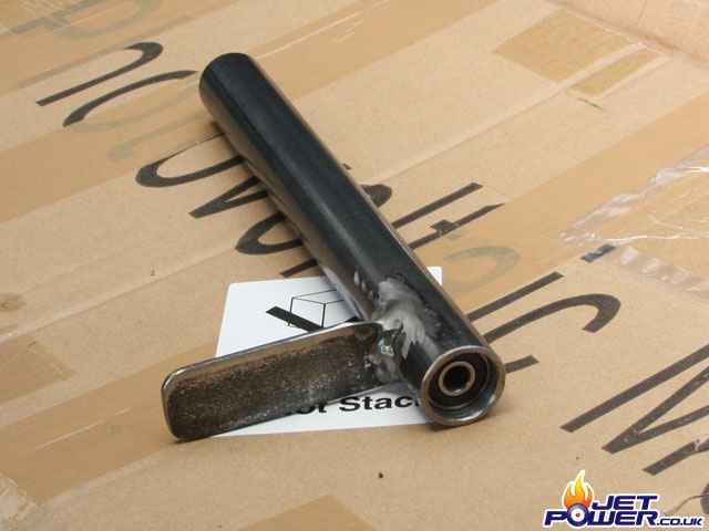
Gear lever to intermediate linkage fabricated, I have used 8mm ball joints purchased from my local kart shop.
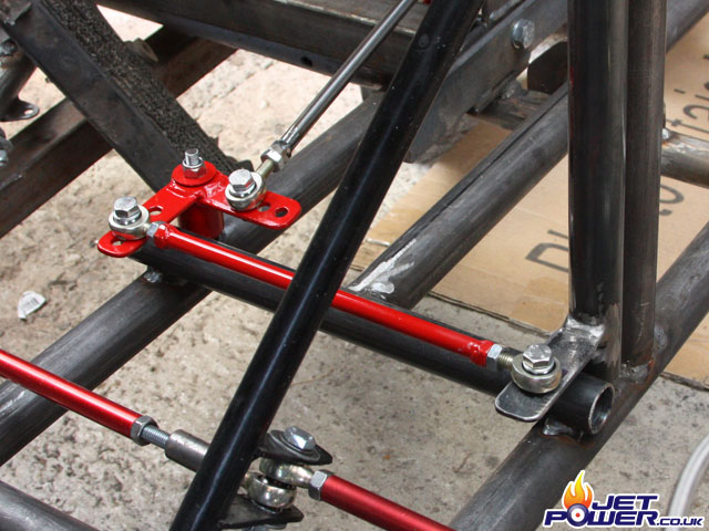
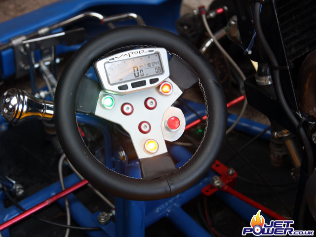
New tiny steering wheel (10″) to help the driver get in and out of the kart.
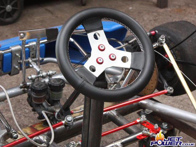
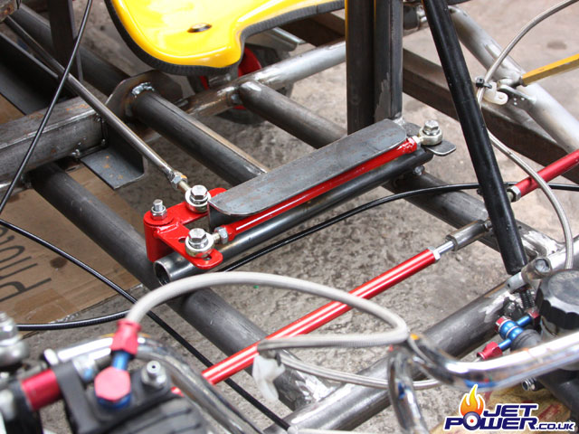
I wasn’t particularly happy with the strength of the clutch and throttle pivots, so I made some more heavy duty ones using 1/4 plate steel.
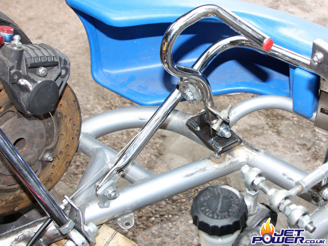
After damaging Phil’s selector linkage on his Kart by standing on it, I have decided that a small length of 40mm angle welded over the linkage should help reduce any damage to it when getting in and out of the kart.
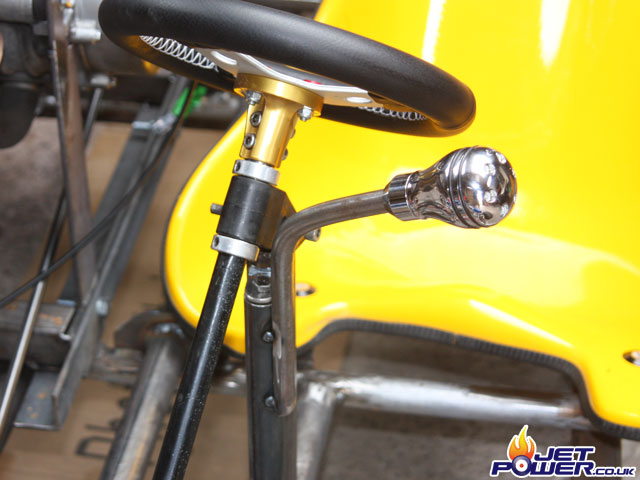
This is my silver ‘Boy Racer’ gear knob that was purchased for my MEV Rocket, but was an SVA failure due to the recessed hex bolts in the centre.
Here you can see the bracket that I have made that supports the HT Ignition coils.
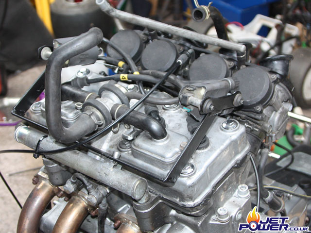
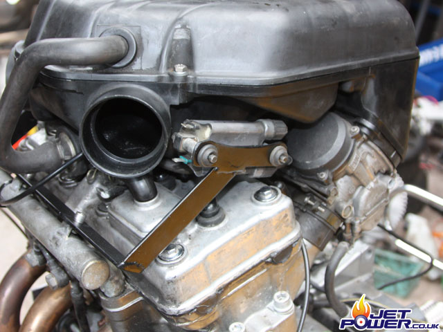
A perfect fit with the air box secured in place.
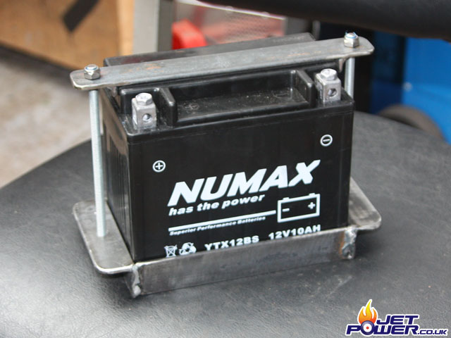
Here is one of my standard design battery mounting brackets.
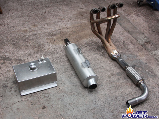
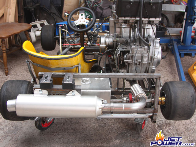
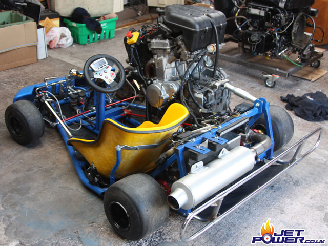
Pictured is my 1.5 gallon fuel tank, modified silencer and exhaust assembly.
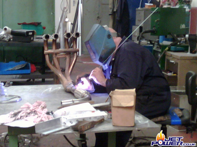
Derek getting the job done.
Fuel Tank, Exhaust and Silencer mounted in place on to a fabricated triangular support on the rear of the kart. Ford Fiesta Engine Mounts have been used to redure stress on the exhaust welds.
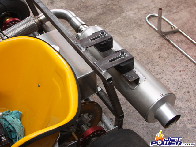
When the engine is moved to adjust chain tension the the slots in the exhaust bracket also allow adjustment of the silencer to facilitate a non-stress fit.
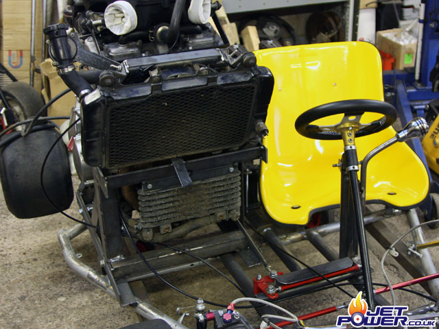
A new radiator and oil cooler mount has now been fabricated, it will be finished off when the kart has a strip down for painting.
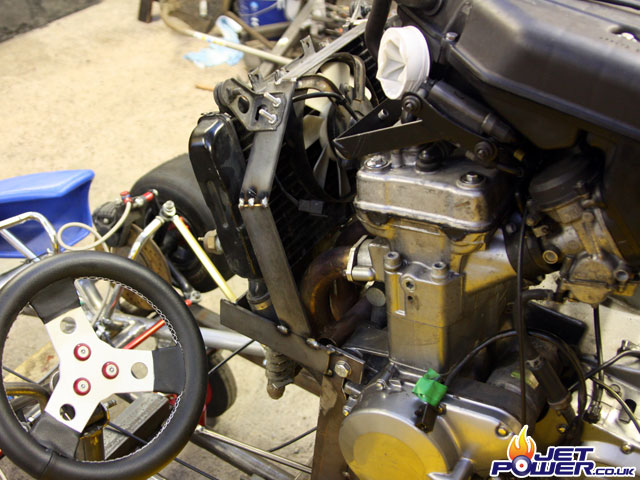
A front view of the radiator mounting bracket.
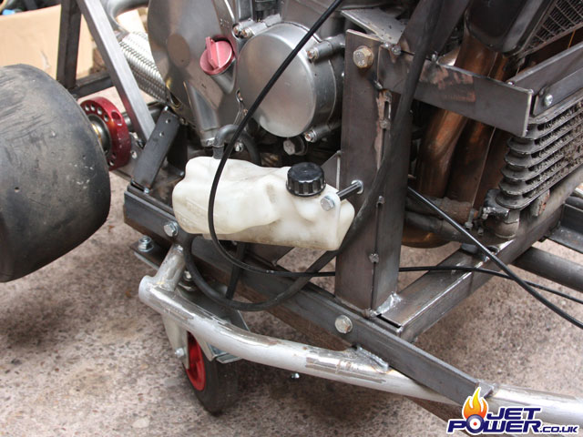
Radiator expansion tank fitted.
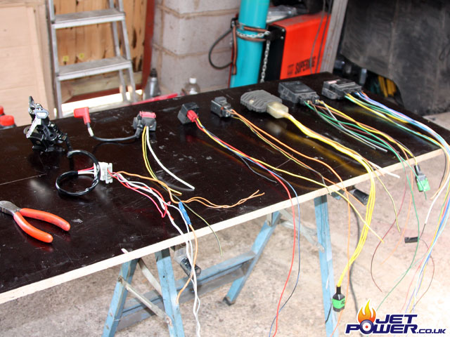
The original bike loom has now been sorted in to the required parts that are needed, all the lighting wiring etc, has now been cut away.
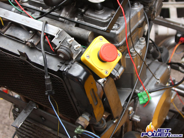
A high visability stop switch, no mistaking what this does, just in case.
Fuel pump fitted and pump relay fitted.
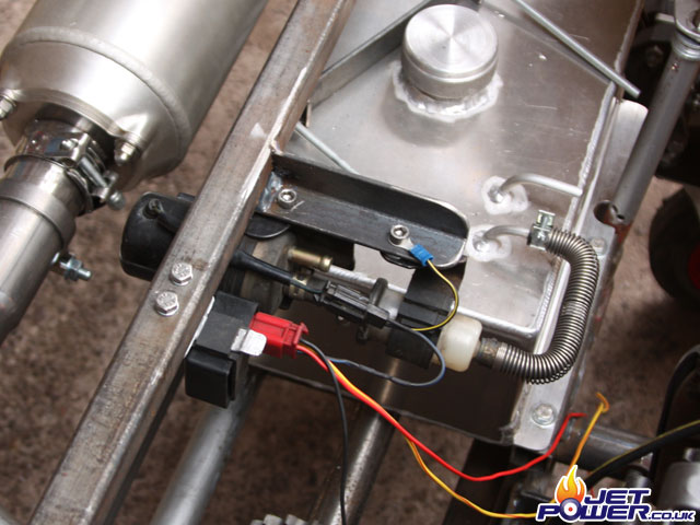
It seemed that I had a totally unique bike and thus no one wiring diagram was correct, so a lot of testing was required, jump leads and multi meters saved the day, anyway I got it to work, and now to tidy it all up.
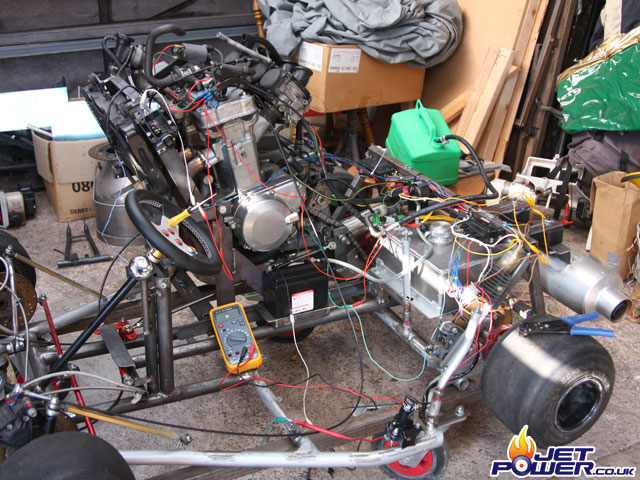
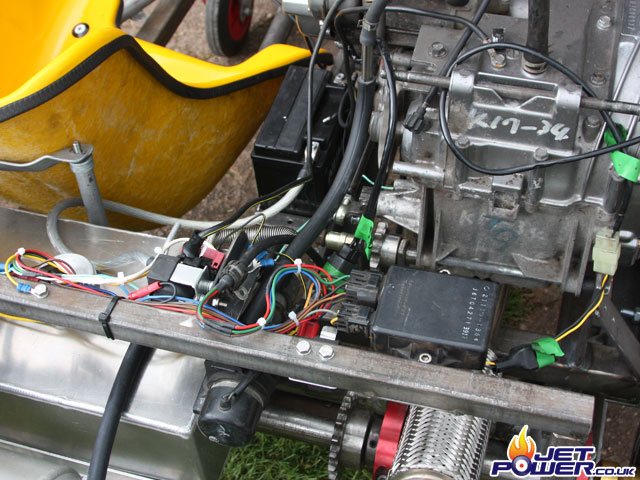
The start of the tidying process, the picture shows the junction/ fuse box on top with the charging regulator shown at the bottom.
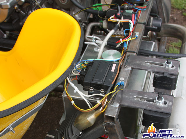
The Ignition unit is shown to the right of the picture, with the fuel pump in the middle and the starter relay to the left.
The steering wheel incorporates the Vapor Digital Dash, also the Neutral, Power on, Oil Pressure warning lights and the starter button.
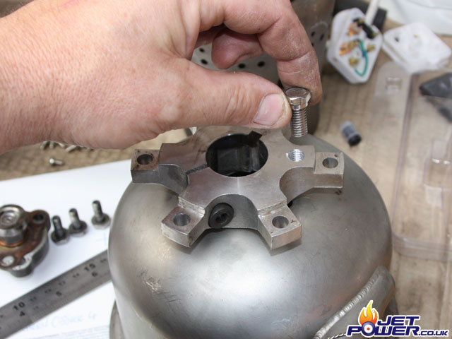
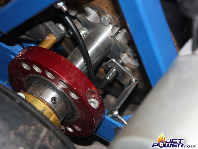
The brake disc boss has been drilled and tapped to allow the mounting of the magnet that the dash uses to measure speed.
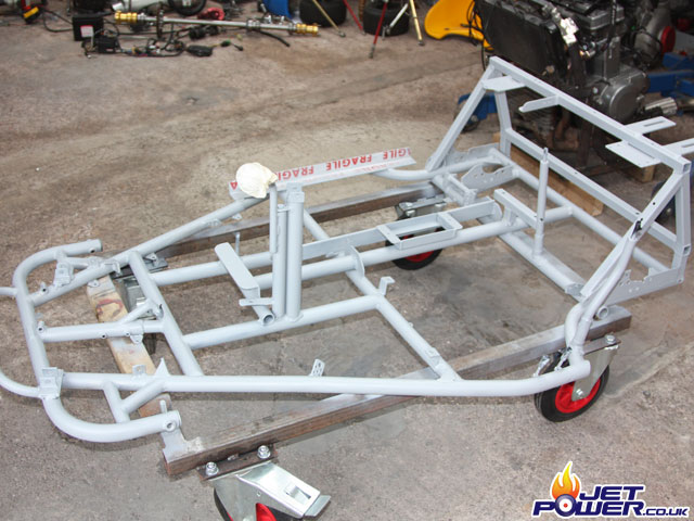
As it’s nearly ready, time for a complete strip down, a degrease and a layer of primer paint.
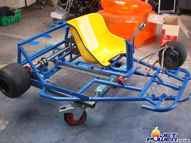
Blue is the order of the day.
The new improved chain tensioner assembly.
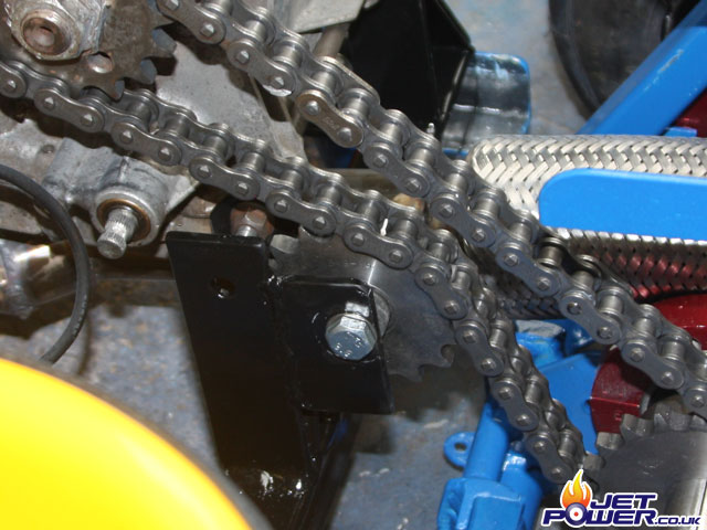
It became apparent that the original sprocket under load was to small, bouncing of the chain when being driven could easily be seen, the new larger sprocket totally stops this from happening.
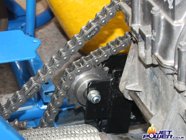
I had a little tootle up the drive and slight flex in the chassis was noticed, not surprising really, so I purchased a top link from a compact tractor, removed the eyelets and welded it to a couple of brackets that attach to the engine and frame respectively.
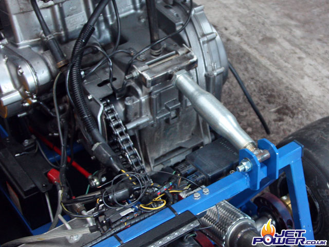
Speedo pick up sensor fitted and what a waste of time, I have to say that I have pretty much given up on getting the Vapor Dash to work with the speedo function, lots of various configurations have been tried and all produce random unstable results.
Just a few tweaks and it will be ready for a trip to the drag strip.
First and last trip, it was fun but I am so glad I managed to make it back home alive. The power in the kart was unbelievable, unfortunately it’s going to have to be sold as its a liability..
