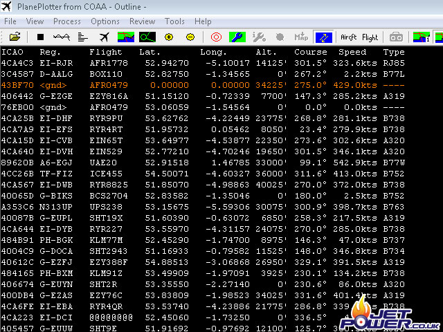
A couple of my friends have been using Virtual Radar for some time now, both use different systems and I thought that as I had a few minutes spare that I should have a go at receiving myself.
Virtual Radar is a way of receiving telemetry data directly form aircraft using radio receivers and/ or by making use of data streamed directly from a Virtual Radar data server. It must be said that with this particular mini project I did have a helping hand from my friend Nic Storey, an expert in Plane Plotter VR!
His informative and helpful website can be found here http://www.nicstorey.co.uk/planeplotter/
Because of the comprehensive setup instructions found on his website, there is not much point me replicating them on this project page, so it will be kept short and sweet.
I have opted to receive data using my own receiver and to also make use at the same time of a Virtual Radar data stream, Plane Plotter is my choice of program because of the unique features it has incorporated. The Plane Plotter website can be found here.
Lets start with the aerial, mine is based on what I believe is an Atouk version. The connector which also forms the main part of the antenna is an SO-239 unit, readily available and only a couple of quid to buy.
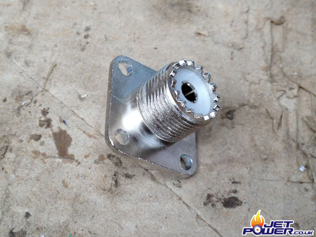
I had lots of trouble soldering the wires to the connector as the internal insulation kept melting, so I have opted to make use of some 1mm copper plate, the wires will be soldered to this.
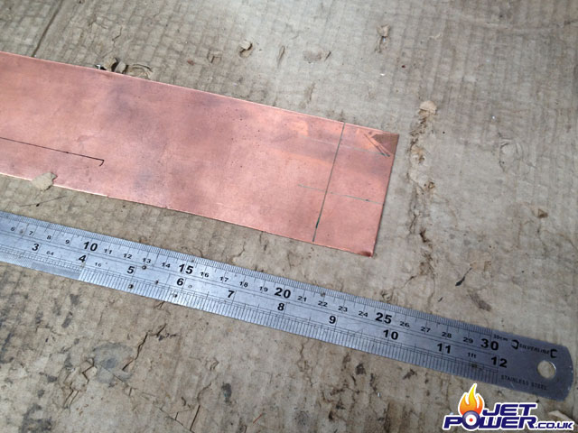
Then I cut some 2mm thick copper welding wire in to 3inch lengths and soldered them to the copper plate. Four 3mm holes were then drilled in to the plate.
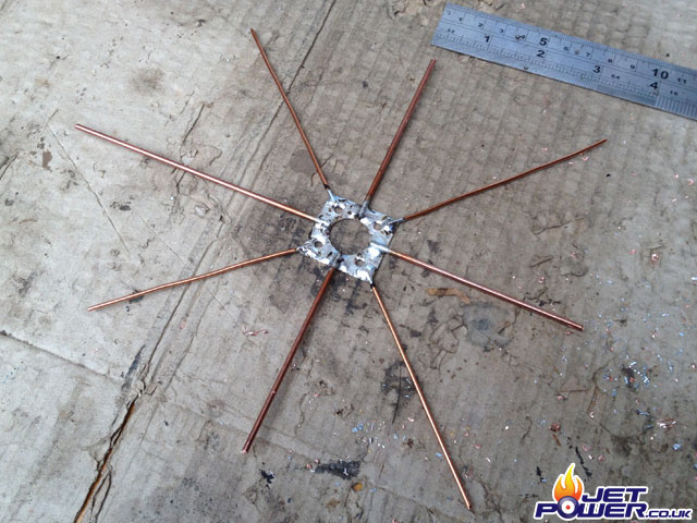
The plate was then bolted on t the connector using 3mm set screws.
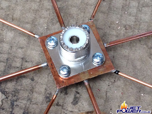
The legs are then bent to 45 degrees and cut to 2.575″ long.
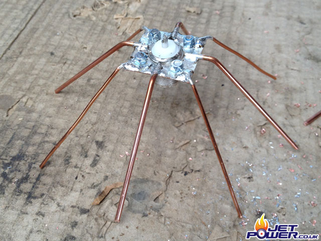
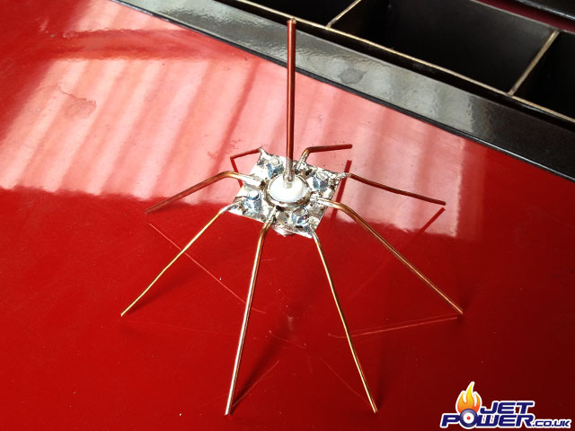
A length of wire also 2.575″ long is then soldered on to the center connection, this is the antenna finished and ready to go, it took about 15 minutes to make and has a 200 mile range!
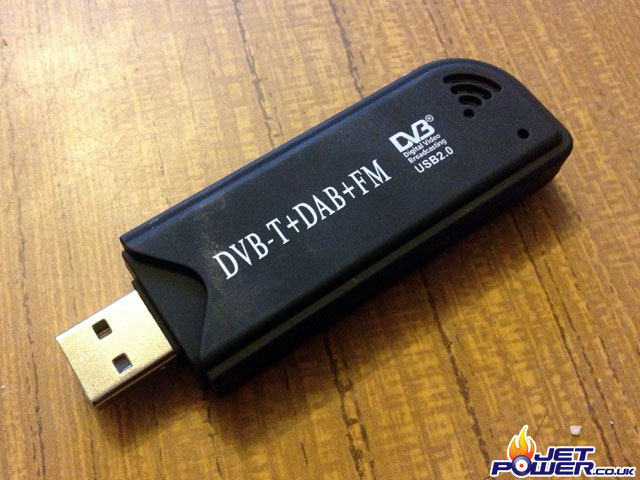
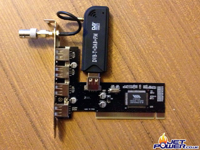
DVB-T Receiver, this one cost £8.00 from Cosy Cave.
Originally used to watch digital TV, some clever people have modified the drivers to that they can receive Mode-S transmissions amongst over things.
To reduce the external profile of my sever, I have opted to make use of a 5 way internal USB PCI card, the only external connection will be the BNC connector which is for the antenna.
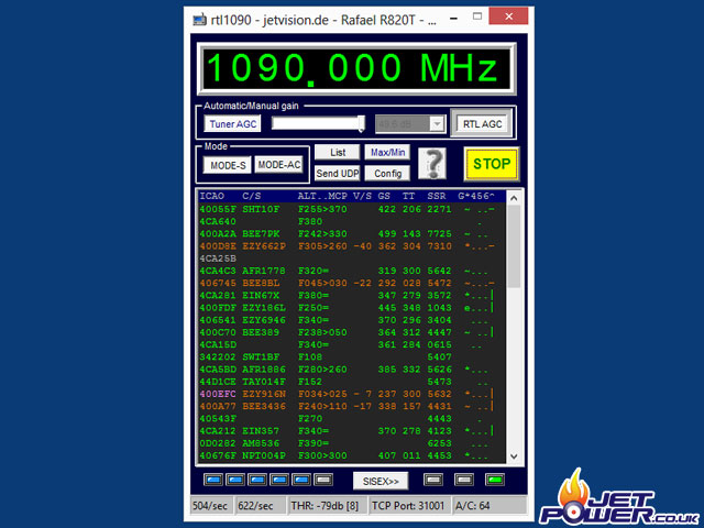
The above screen shot is the RTL software functioning, this is the raw data the planeplotter will use for its plotting, you can see that the status bar at the bottom left is at it’s upper end of the scale.
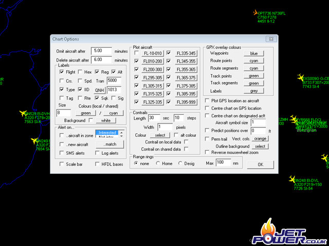
Planeplotter Software screen shot.
An example of one of the views that PP provides.
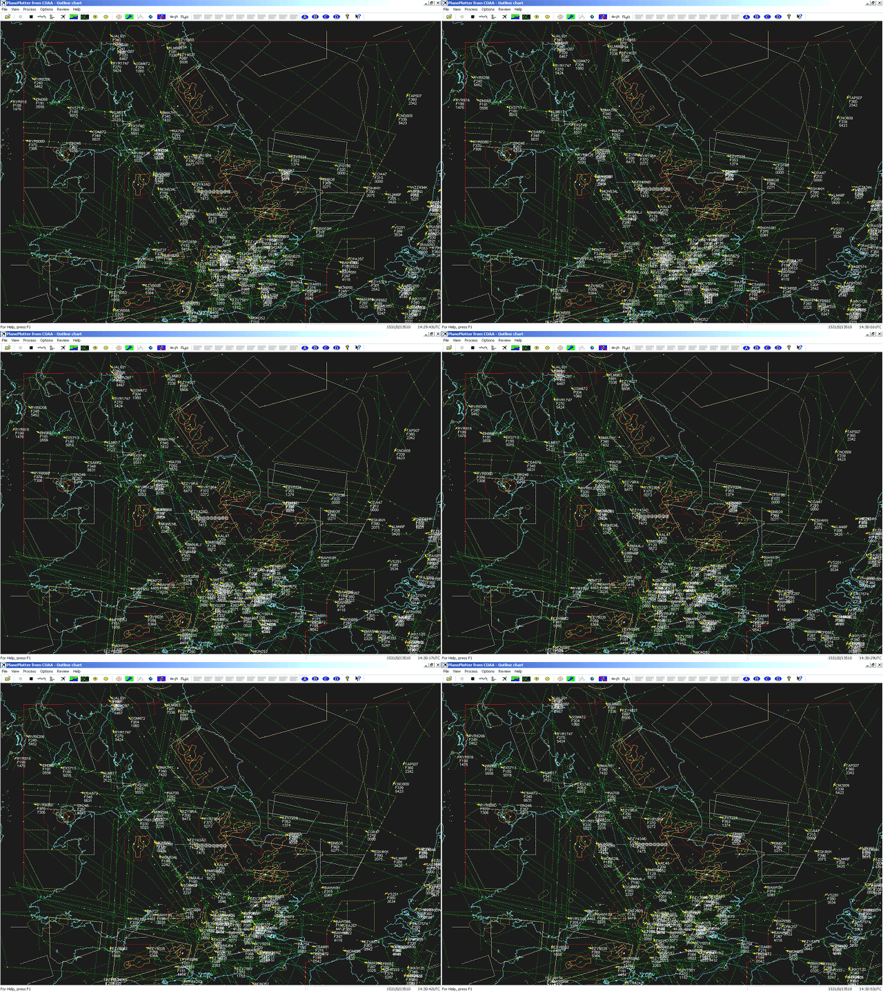
An example of a data stream from plane plotter.
