What’s the point in having a homemade jet engine if it’s not going to be put in something?
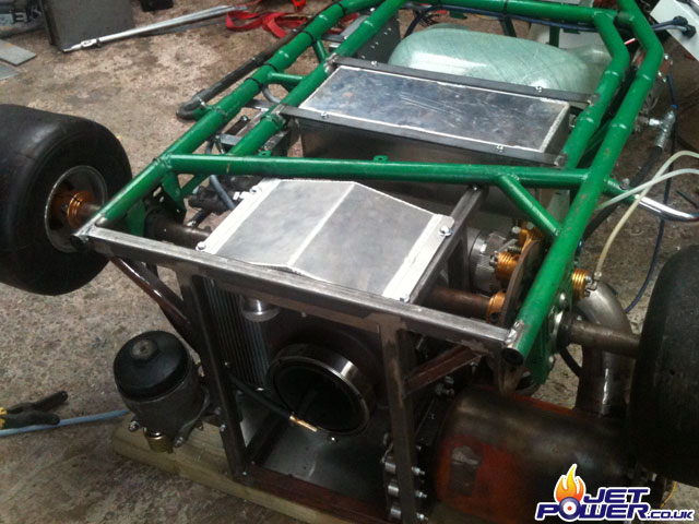
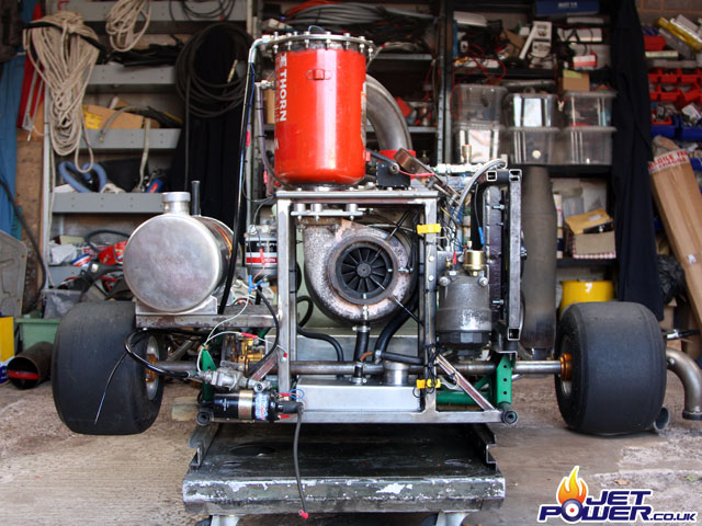
As pictured you can see I intend to mount the combustion chamber horizontally in an attempt to keep the COG low.
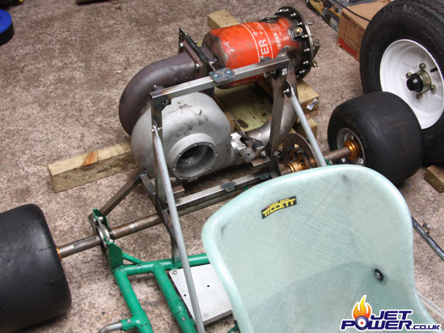
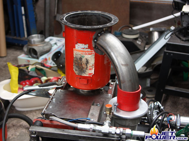
I’m happy with the position of the engine as shown above, the supporting frame will now be reinforced and this will also allow spaces to mount all the accessories required to run the engine.
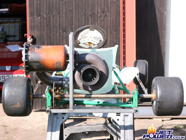
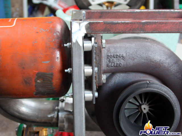
To reduce heat transfer from the turbo mounting plate to the supporting frame, spacers have been added so that there is a reduced metal to metal contact surface area.
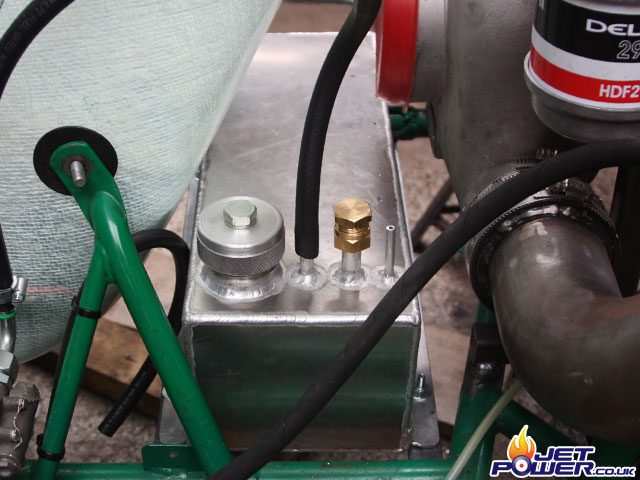
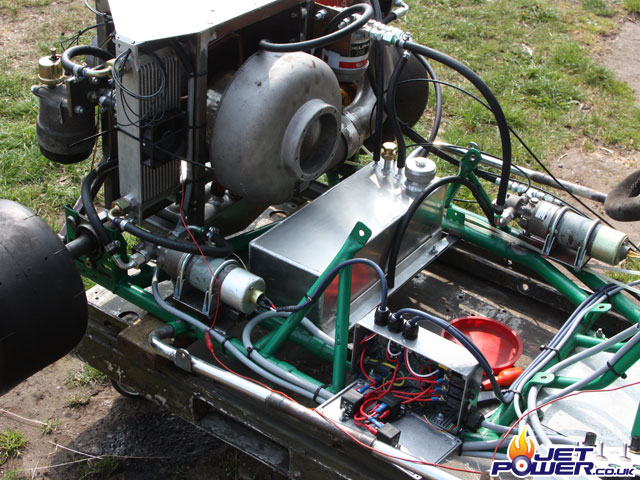
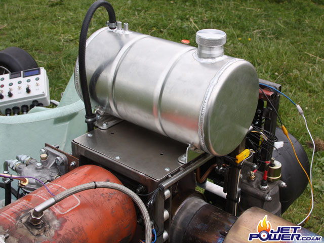
The oil tank has now become the fuel tank and sits comfortably behind the seat. Brackets were welded on to the kart’s frame to facilitate this.
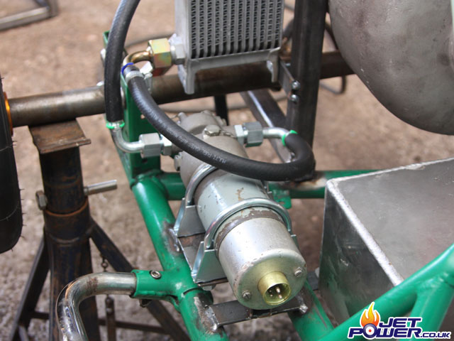
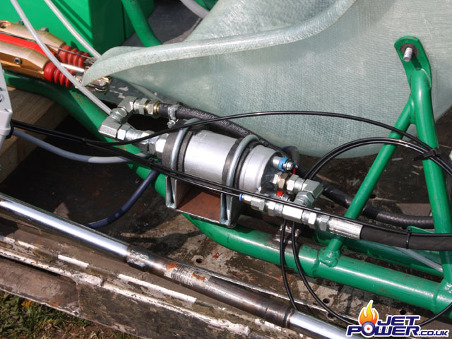
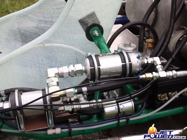
I have decided not to use the automotive fuel pump that was originally in the static engine setup, but a Plessey aircraft fuel priming pump.
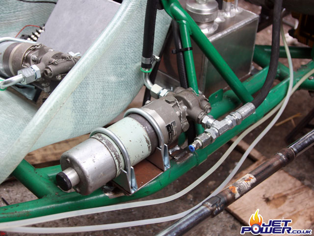
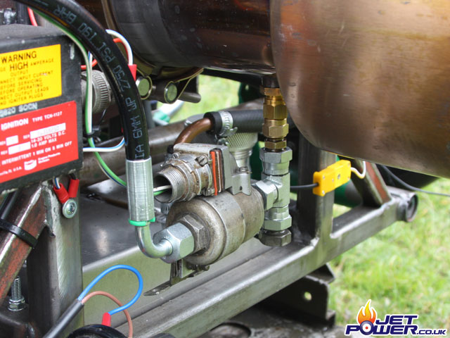
The fuel system so far; Tank to the CAV filter, then to the pump and then using single wire hydraulic hose to the HP Cock which is connected to the injector. I have added a Tee and a Presto-Lok type connector at the pumps outlet so that fuel pressure can be monitored.
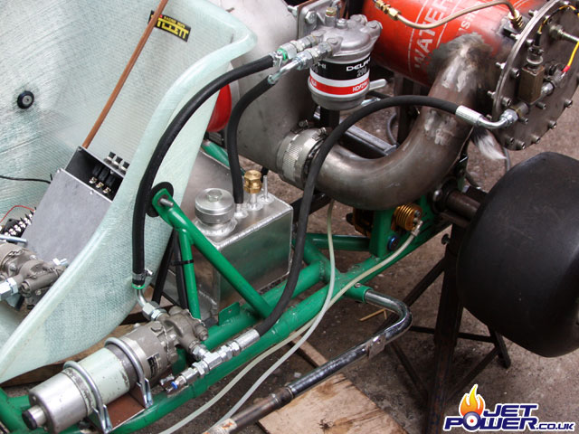
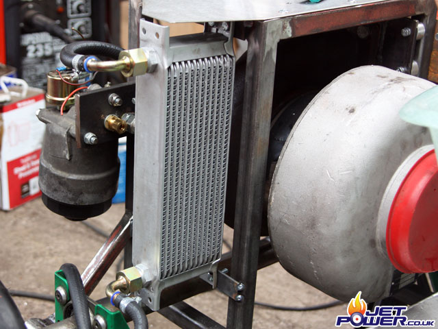
Now moving swiftly on to the oil system, pictured is the oil filter assembly fitted to the rear/ side of the engine frame, maybe not an ideal location in terms of it’s proximity to the hot end, but it does make the plumbing a lot neater.
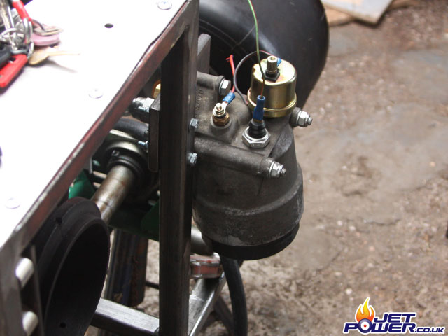
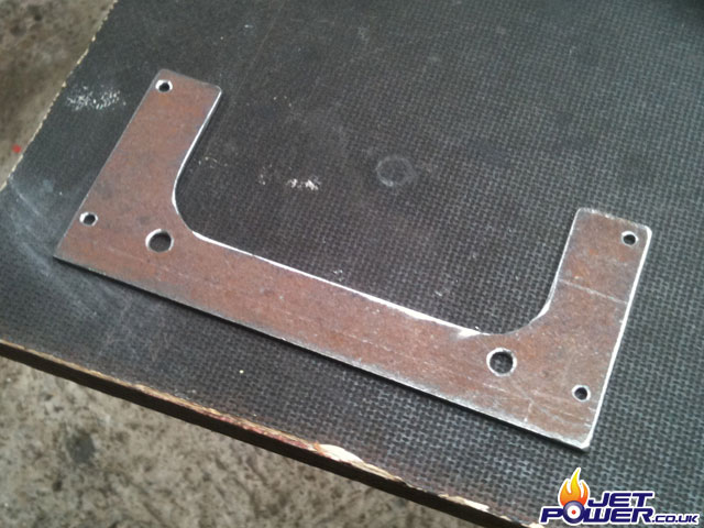
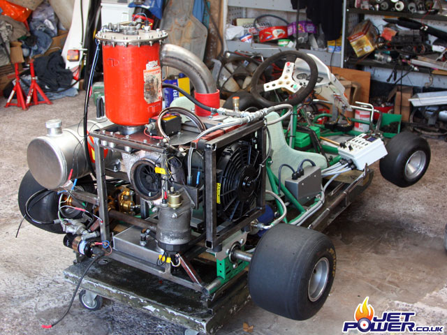
The oil cooler has now been mounted vertically and the oil flow will be from the bottom upwards, this will avoid air pockets forming in the circuit. A stainless top plate has been added with a protruding section that hopefully will give the oil cooler a small amount of protection from knocks.
Out on a limb with this one as I haven’t tested the Plessey pump with a pressurised oil flow, if it struggles or it simply can’t handle the viscosity then I will replace the pump with the original one used.
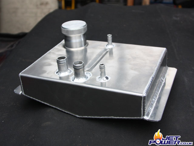
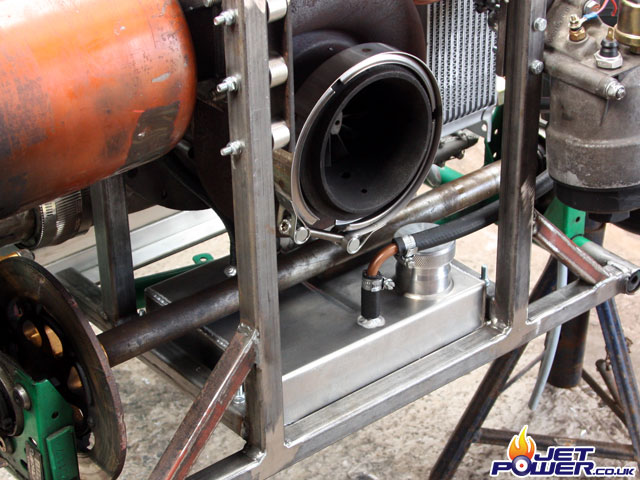
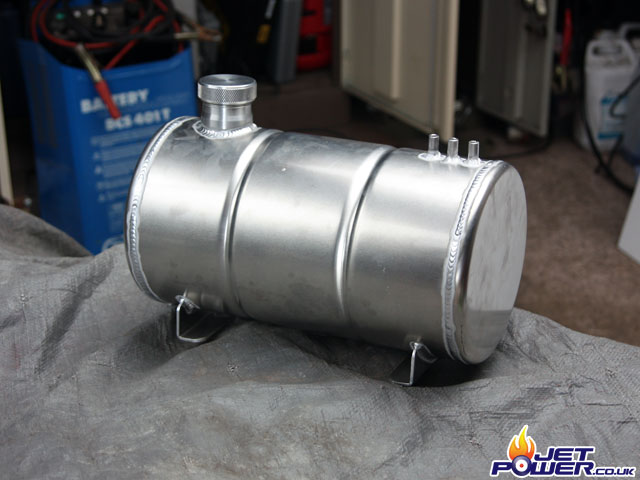
I have designed the oil tank to sit comfortably directly below the turbo to aid oil drainage, RJS Fabrications made this one and I have never seen such craftsmanship – highly recommended.
Mounting holes were drilled and the tank was fitted to the chassis, the tanks return pipe is now connected directly to the turbo using about 3″ of 3/4″ high temperature oil pipe.
The oil supply pipe is shown at the rear with the oil coming from about 1/8″ above the bottom ‘ Vee’ of the tank. I do have concerns about the amount of oil being used and the high temperatures due to a lack of volume, I’m hoping that the oil cooler will do it’s job passively, a fan can always be added at a later date if necessary.
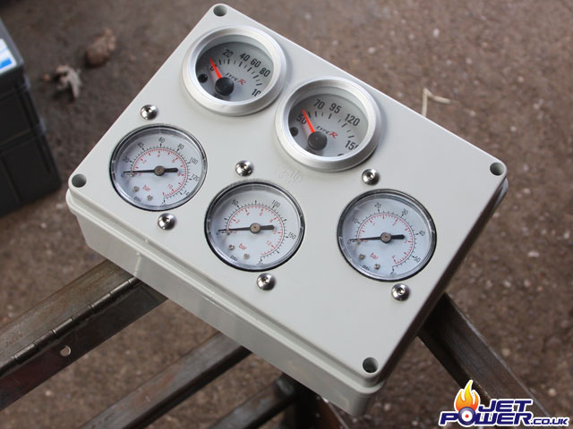
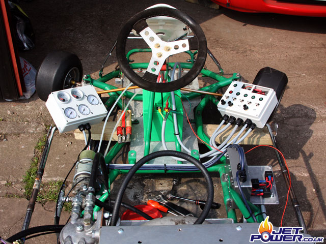
I have decided that the main engine gauge console will be mounted to the left hand side of the kart chassis, there is electronic oil psi/ oil temp gauges along side of turbo fuel, re-heat fuel and P2 pressure gauges.
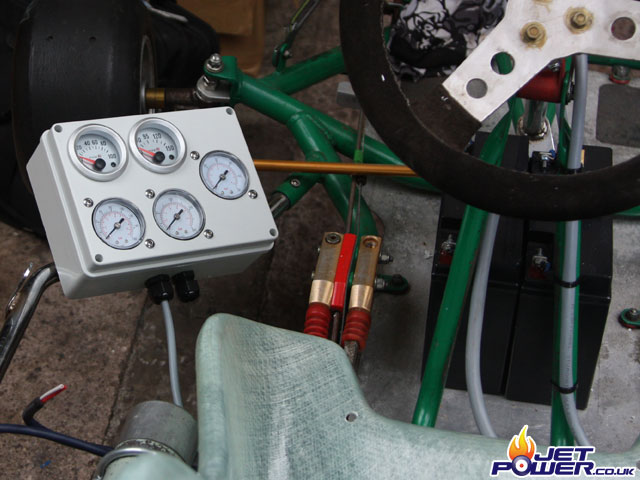
The gauge console has now been mounted to the kart’s frame, the wire is a seven core cable that terminates inside the switching control panel, the three 4mm pressure pipes that feed the analog gauges have yet to be installed.
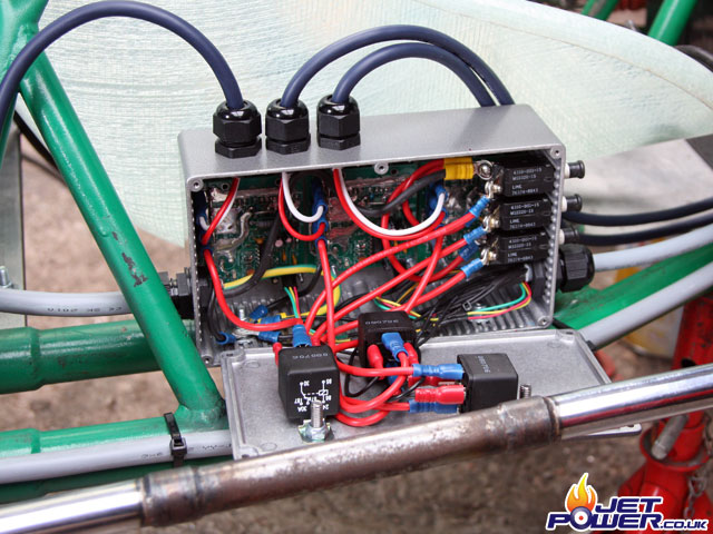
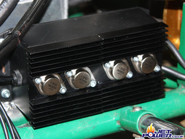
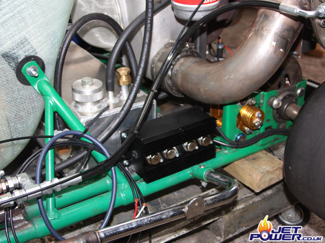
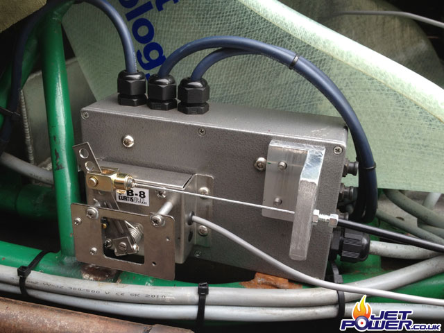
Pictured is the control box that will ultimately power the three electric pumps, potentiometers that will be mounted on an adjacent control box to the gauge panel will allow for the oil and fuel flows to be adjusted, a bit more work till this is completed. In this photo you can see three speed controllers with three 15amp circuit breakers mounted at the top.
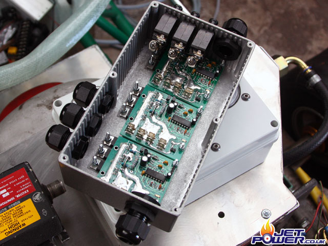
Speed control box finished, room was getting a little sparse by the time the on/ off relays were added.
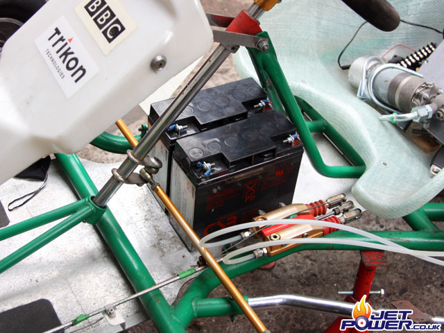
The two 12 volt battery’s (wired in series) fit neatly below the steering column in between the drivers legs, a bracket will be made to hold them together and in place. The two battery’s provide all the energy required to run the kart’s electronics and pumps.
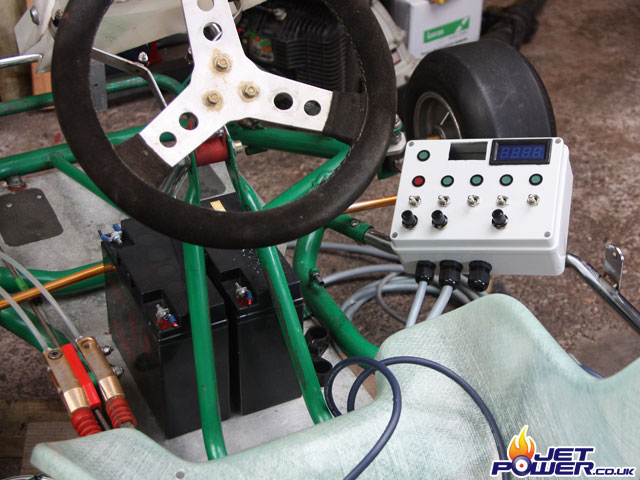
Drivers view of the switching control panel,
From the left;
Oil Pump Pot, Switch & Indicator (Red & Green)
Turbo Fuel Pot, Switch & Indicator
Turbo Igniter Switch & Indicator
Reheat Fuel Pot, Switch & Indicator
Reheat Igniter Switch & Indicator
24v Volt Meter & 50amp Ammeter
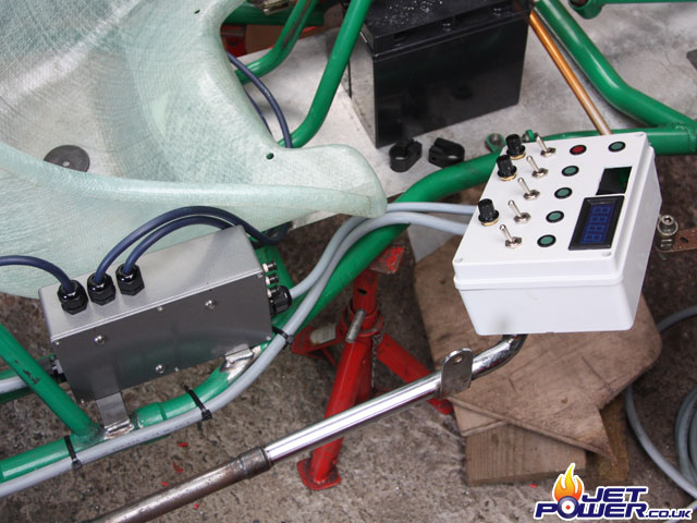
A view of the speed control box and switch console.
The blank space upper right is for the voltmeter which has yet to turn up.
Time to get this mess wired up, the left the cables come from/ go to the speed control box, Power from battery, Power to Speed control box, To RPM/ EGT display yet to be fabricated behind wheel, To gauge Console,To rear of the kart (Thermocouples, Igniters etc)
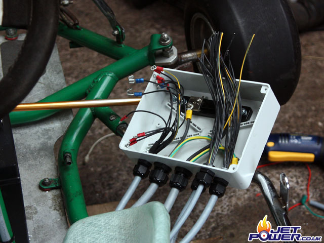
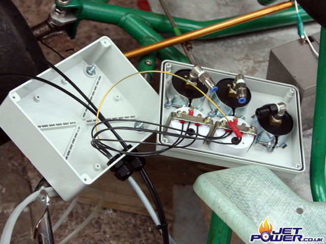
Another 10 minute job out of the way, the oil temp and oil pressure gauges have been independently wired up and the three 4mm pipes from the pumps and P2 have been connected using Presto-Lok fittings.
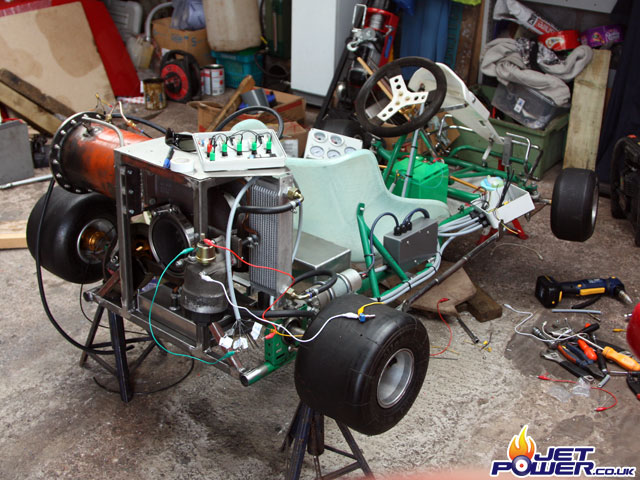
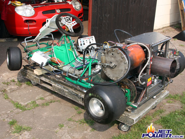
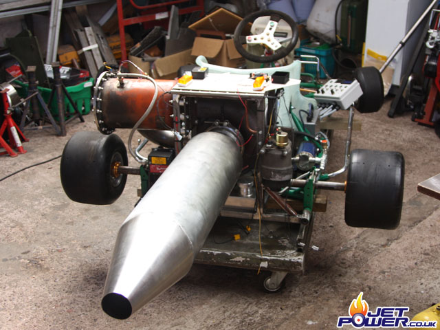
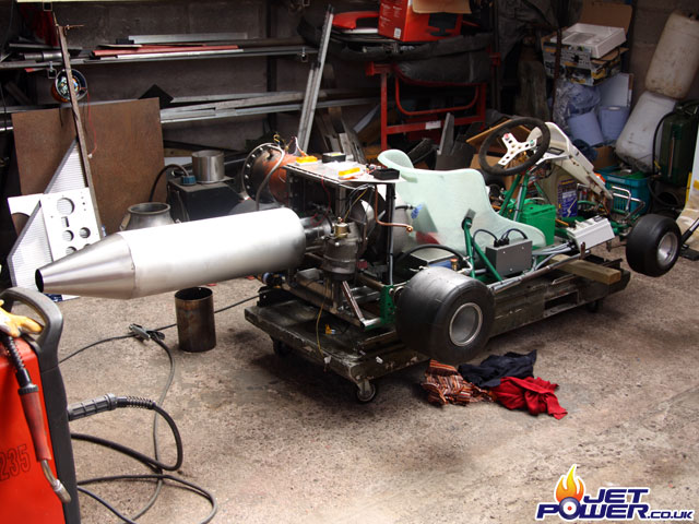
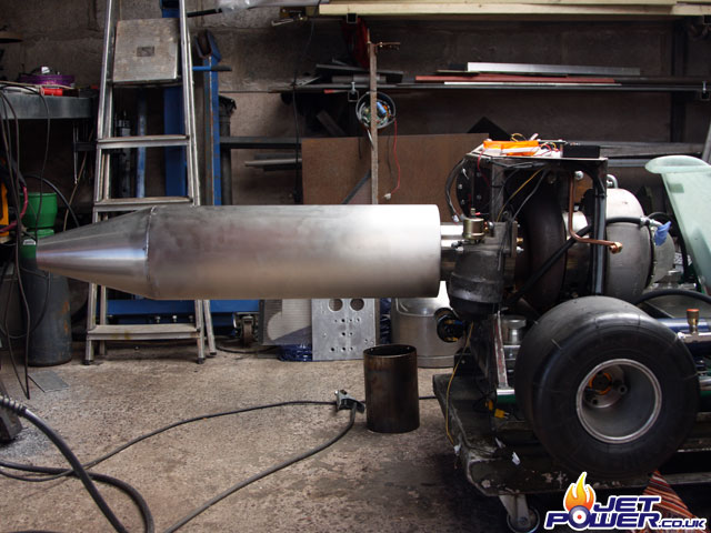
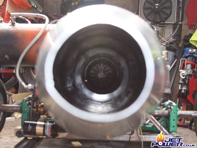
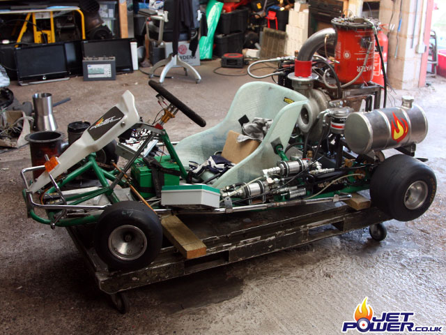
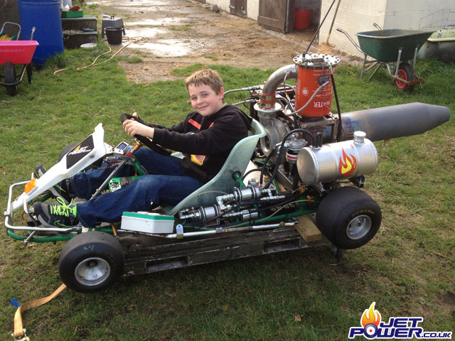
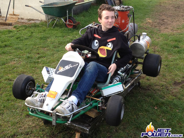
A view of the kart as of the 16th April 2011, another good days work and it should be finished, all that will be required is the propelling nozzle. I guess I better make an afterburner for it.
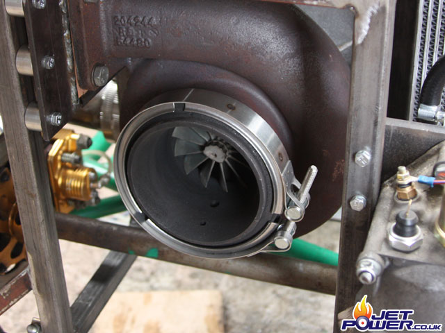
I managed to source a V-Clamp from my local commercial truck dealer, I feel it was a bit of a bargain at £25.00, any one else wanting one should go to their DAF agent and ask for part number DA1290255.
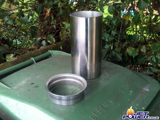
The 5″ flare pipe that match’s the turbo and the v-clamp was sourced from the same DAF dealer, possibly not a genuine DAF or Volvo item but a deal at £24.00 – part number DI78228.
A drivers eye view of the controls as they are at the moment.
Cross side on view of the kart.
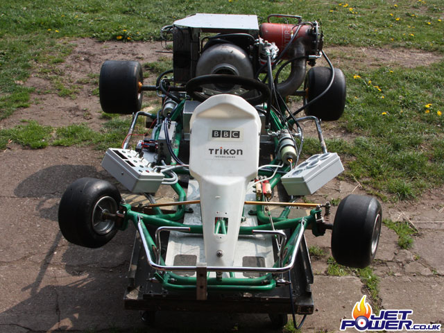
The engine has had a run in it’s new environment. Today has been a bad day and I have learned a few lessons about continuity.
The engine in the static frame would run very nicely and without any issues, of course I have now added to and taken away a load of features that have proved detrimental to the performance of the turbine, coupled with some good old fashioned bad luck, I currently feel quite hard done by.
- The oil pump doesn’t like hot fluids and the pressure drops to 20psi when running, it can maintain a happy 60psi when the oil is nice and cool and thick.
- The oil cooler even with a blower cannot seem to cope with the heat and get’s hot pretty quickly. A larger cooler and fan assembly will be required.
- The fuel pressure gets erratic at 160psi due to the pump not being able to cope with the flow and pressure required, a shame as my target is 170psi.
- One of the speed controllers packed up.
- A 30amp speed controller relay failed.
- The wire in the fuel pressure hydraulic line earth’ed the pump to the chassis ultimately destroying another speed controller.
- The digital ammeter IC chip blew a hole in it’s self.
The list goes on, part of the fun I guess.
Back to the old faithful Bosch 044 car pump, I just need to get rid of the braided fuel pressure hose and it should work as well as before. The pump is mounted using the same exhaust clamp as the plessey pump, but due to it’s small diameter a layer of rubber can be wrapped around it insulating it from the kart.
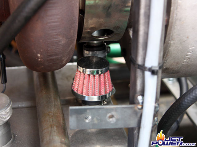
I have attached an oil breather with an 18mm gland that fit’s nicely on to the oil tanks breather port, I may yet have the breather vent to the inlet of the turbo, but with the extra pipe work needed and lack of space this way will do for now.
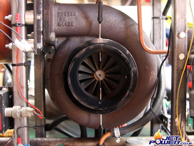
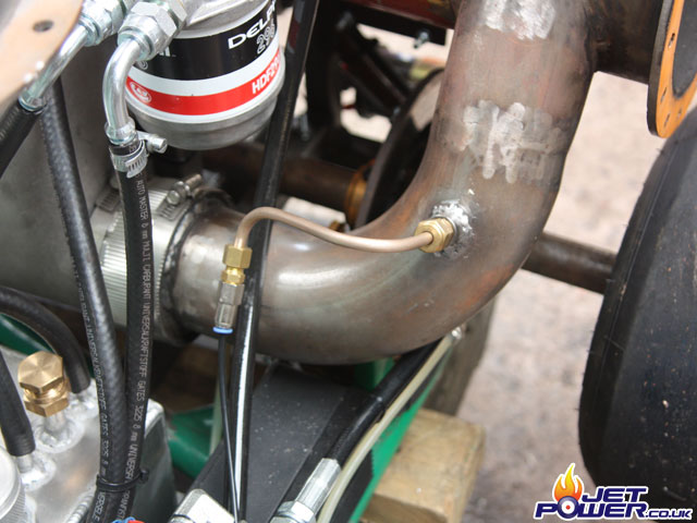
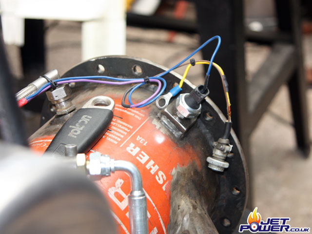
I have drilled and tapped an extra hole in the turbo so an extra thermocouple can be added to increase accuracy of the exhaust temperature readings.
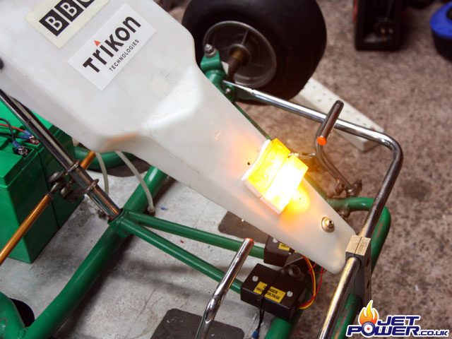
And to fill a hole that was in the front cowling, I have added a couple of strobe lights, just for show.
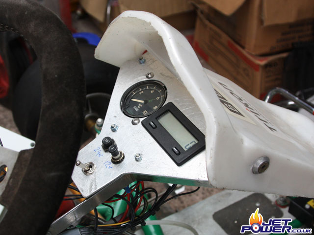
The center instrument panel incorporates an EGT gauge, Red Lion Counter for RPM, a 24volt 30amp breaker and a 12volt 3amp breaker. The switch below turns the strobe lights on and off.
Daily Main Feature which kind of reads:
‘Big bloke who is large builds jet kart, which would go faster if he lost weight and was less fat’.
Nice……
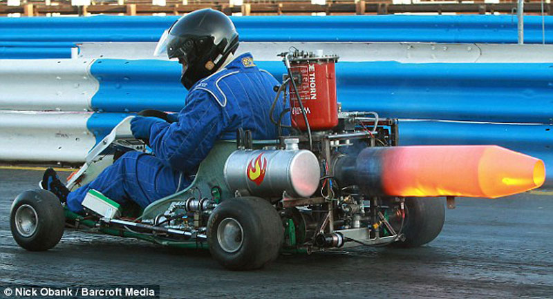
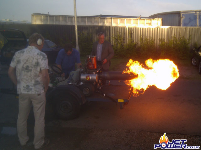
First run and low power test (about 40% turbine power) of the afterburner, good results!
A couple of runs which result in the tripping of the 15A fuel pump circuit breaker. Time for a bigger injector nozzle.
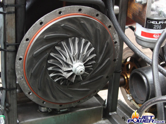
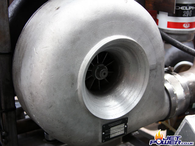
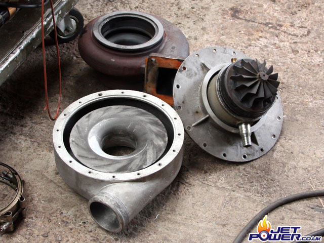
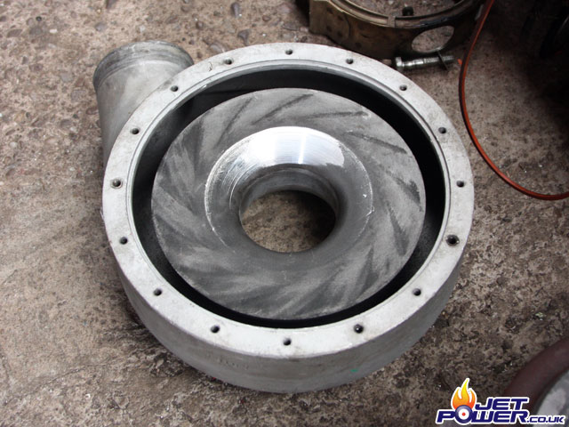
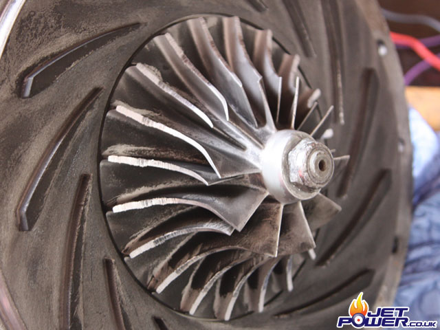
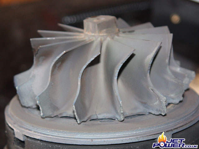
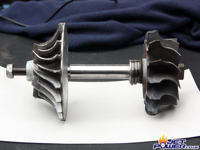
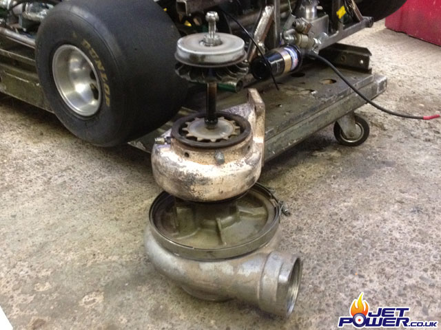
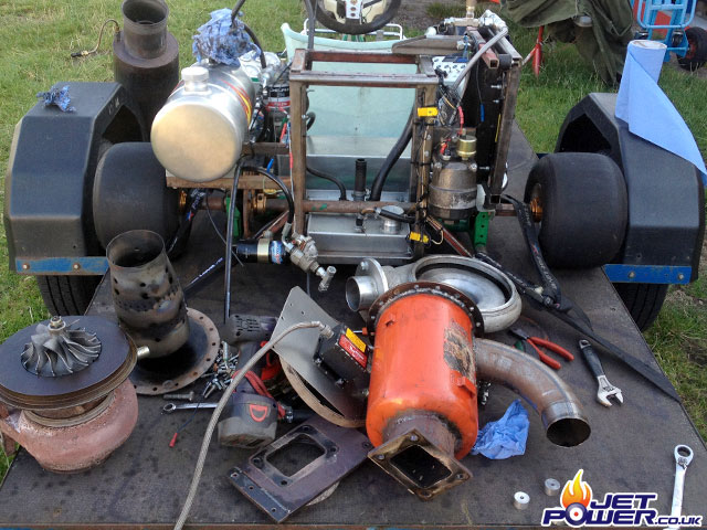
Run and failure of the Cummins VT-50 turbo. Now moving on to a slightly larger Schwitzer turbo.
First run of the Kart since the new Schwitzer turbo has been fitted. Initial ignition is poor, possibly from having the injector nozzle to large, I will try a couple of sizes down to see if it improves.
